Running on an embedded system, sometimes the memory will be very constrained for the Sparklet. In some cases, there may be dedicated memories GPU-Only, VRAM etc., residing at different locations. This calls for a dedicated memory layout for each target/use case.
It is essential for the user to create a memory layout to be used by the internal memory allocator.
To define the same, select flint.efp file. Select the Memory and Storage tab and then click Add button. The following fields will be requested.
Memory Type: Used to set the type for the memory to allocate
Internal VRAM
External SDRAM
Internal SRAM
Start: Indicates the start address of the memory region, say 0xC0000000.
Start Is: Indicates the type of Start value
Address – Not supported
Value – To get the value from
Auto Allocate – Auto allocate memory from system heap
Size: Size of the memory region
Block Sizes: Comma separated values. Can be used to defined block sizes say 1024 or so. Useful in case of fragmentation issues.
Provide values for Memory Type, Start, select Start Is value, Size and Block Sizes (External SD RAM, NULL, Auto Allocate, 16777216 in this case).
Sparklet Run Time Engine, as with any software, needs memories for proper operation. Whether it is the read-only storage for storing the asset and meta information or the read-write memory to store the frame buffer and the temporary data, different types are used based on the necessity.
This section provides a general overview about the memory consumption and way to configure the uses as per the user requirements.
On the run-time environment, the memory organization looks like depicted in the below picture.
The Sparklet engine along with the application logic sits on the code area and is executed by the processor core. The Flash output image exported (typically in .srec or .bin format) is stored in some read-only area and the starting address of it provided to the Sparklet run-time.
The underlying design could leverage multiple memories to store the temporary data. These are configurable as memory pools. The picture shows 3 memory pools each sitting on VRAM, SRAM and SDRAM.
It is possible to configure Sparklet to use VRAM region for storing frame buffer, SRAM for caching and SDRAM for other image related information.
This section provides a general overview about the memory consumption and way to configure the Sparklet as per the user requirements.
Every Flint project leverages assets for generating a meaningful user interface. It could be fonts to render textual information, images to show graphical information or specialized formats such as nine-patches etc. Also, meta data like the location of these assets, data variables and their information, state machines used in the project etc are also needed for the proper run time operation.
Both this information is stored typically in Read-Only memory. As explained in the earlier section, the Storage tab in the Flint Project Editor allows definition of such memories. It could be internal Flash or memory mapped external flash based on the target architecture. The Images tab allows fine control of placement of images in one of the defined Storage areas.
All the meta-data are placed, by default, in the first defined Storage area.
The approximate memory consumption of the Storage area can be obtained by reviewing the Memory.csv file created when exporting the project.
The typical output looks like this.
As can be seen, the parameters Path, Storage, and Size have been specified. The total memory usage (in bytes) can be obtained by adding the values of the third column.
In this case, total memory usage is approximately 418304 bytes.
It is critical for Sparlet to have read-write memories so that various temporary data can be maintained over the course of execution. The Memory Tab allows user to define the available memories in the system along with their address and size.
Based on the target architecture, VRAM, SRAM or SDRAM can be defined in any number of pools.
Since the Sparklet uses a block memory allocator for this purpose, the sizes of blocks can be specified too.
The information about configuring the Memory Tab is captured in our earlier section on Project Editor.
It is important to understand the run-time memory requirements of Sparklet before we attempt to configure them.
Undoubtedly, one of the most components is the Frame buffer. Sparklet uses two frame-buffer concept – one front and another back buffer. The Front buffer is always shown on screen while the rendering is done on the back buffer.
Once it is completed, the buffers are swapped.
Size:
The size of the frame buffer depends on the resolution of the display and the size of each pixel. While the width and height of the display is defined by means on the Flint Project, the pixel depth depends on the target architecture – for e.g., 2 bytes for Renesas RA6M3, NXP iMxRT, and 4 bytes for Renesas RH850, Linux and Windows simulation.
Placement:
The Frame buffer always sits on the first hardware layer memory defined in the EFP- Layers tab.
In some cases, there might be a need to separate out certain widgets to different hardware layer to achieve faster rendering. These hardware layers are defined in an EFL file and each of the widget could be assigned to any one of these layers in the Placeholder’s Layers section. Again, each of these layers are allocated twice for front/back display/render mechanism.
Size:
The size of the hardware frame buffer depends on the width and height of the layer and the size of each pixel. While the width and height of the display is defined by means on the Flint Project, the pixel depth depends on the target architecture.
Placement:
The layers are allocated based on the set memory region.
As the asset information is stored in read-only memory there are some more information that are needed to be changed dynamically such as the current frame being displayed etc. This calls for some run time memory.
Size:
The image information needs 80 bytes of memory per image used in the project.
Placement:
Placed in the first defined memory pool.
If any image is marked as not in place in the Images tab of the Project editor, then a memory equal to the image format is allocated from the Load memory pool.
Size:
The size allocated will be the product of its width, height and size of the format (4 for ARGB888, 2 for RGB565, 1 for A8 etc).
Placement:
Placed in the memory pool selected as load area.
As with the non-in-place images, Animated EFX images needs RAM region but twice the amount if pre-load is selected so that a front region and back region can be used.
Size:
The size allocated will be twice the product of its width, height and size of the format (4 for ARGB888, 2 for RGB565, 1 for A8 etc).
When Sparklet is running, it frequently access the widgets via IDs to do operations such as drawing, handling mouse inputs etc. Originally organized as a tree, it is time consuming to search the widget based on the given widget ID. But this search can be significantly improved if there is a cache available where the pointers of the widgets are maintained. Flint provides a way for the user to specifically define the pool to use for this look up table information (cache).
Size:
The lookup information needs 2 bytes of memory or 4 bytes of memory (based on underlying target architecture pointer variable time) per widget used in the project.
Placement:
Placed in the user defined memory pool in the Misc Property Tab of Project Editor (EFP).
For various internal operations such as widget memory allocation, image cache etc, Sparklet uses a default memory pool. This default pool can be selected from one of the defined pools from this selection.
Note: This is currently not consumed in Sparklet and is used only for memory calculations as of now.
Size:
The lookup information needs 2 bytes of memory or 4 bytes of memory (based on underlying target architecture pointer variable time) per widget used in the project.
Placement:
Placed in the user defined memory pool in the Misc Property Tab of Project Editor (EFP).
As we are aware, more than one pool can be configured and the use of them can be controlled through one of many ways as will be explained above.
Typically, the images occupy a large portion of memory. Flint allows the user to configure the location to place the image (Internal/External flash), Color formats (PNG, ARGB8888, RGB565,RGB888, CLUT, A8), In place loading feature as well as optimization types.
To keep track of updates and release of packages, each release is assigned a unique identifier that consists of a four-part version number (Major.Minor.Fixes.Build). This is helpful in determining whether the newest version has changed a small amount or quite a lot since the previous version.
To optimize the performance, it is possible to cache the widget lookup table during the execution of the Sparklet engine.
Use this option to select the memory region to place the lookup table or none to disable it.
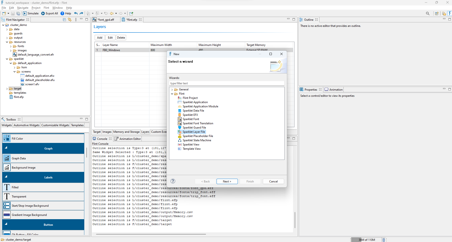
In certain instances, it may be necessary to assign specific widgets to different hardware layers to enhance rendering speed. This can be achieved by creating a layer file under the target folder.
To create layer file (EFL) in flint, right click on target ->New -> Project.
By selecting on the project click Flint->Export All. Sparklet.bin and other necessary files are generated in the output directory.
The Flint builder processes files one by one, validates them and converts them to a binary format that can be read by the Sparklet engine. On course of build, errors cause build failure and warnings may cause UI artifacts. Carefully sort out the issues.
Up on successful build,copy the Sparklet.bin file generated to the target in a way suitable/prescribed for that device. Launching the application will show the designed screen in the device.
Flint offers the flexibility to simulate the whole design in the PC before even deploying the project. To achieve that, by clicking on that project, select Flint -> Simulate.
Whenever needed, the Flint project properties can be edited by opening the project properties section. To do the same, right click on the project and select Properties option in the pop-up menu. A dialog will be shown with a list of groups on the left.
Select the Flint option there and on the right, the Project Properties page will be loaded. Edit the fields as necessary and apply changes for them to take effect.