Logical Groups
Overview
These blocks are used for Logical operation of a given input.
Logical OR
Logical AND
Logical NOT
Logical XOR
SR Flip-flop
Toggle Flip-flop
Data Flip-flop
Latch
Logical OR

This block is used to find the Logical OR operation all the inputs and store result in the output.
Properties Name
Description
Number of Inputs
Number of Inputs to be Logical OR
Inputs and Outputs Name
Description
Supported data type
In – Input 1
Input 1
In – Input 2
Input 2
In – Input n
Input n
Out – Output
Logical OR value of all input values
Logical AND

This block is used to find the Logical AND operation all the inputs and store result in the output.
Properties Name
Description
Number of Inputs
Number of Inputs to be Logical AND
Inputs and Outputs Name
Description
Supported data type
In – Input 1
Input 1
In – Input 2
Input 2
In – Input n
Input n
Out – Output
Logical AND value of all input values
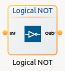
Logical NOT
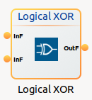
Logical XOR
SR Flip-flop

This block is used to find the SR Flip-flop of given inputs and store result in the output.The output is the logical set/reset value.The truth table as shown below:
Clock input |
Reset input |
Set input |
Output |
|---|---|---|---|
Low(0) |
Low(0) |
Low(0) |
Previous state |
High(1) |
High(1) |
Low(0) |
Low(0) |
High(0) |
Low(0) |
High(1) |
High(1) |
High(1) |
High(1) |
High(1) |
High(1) |
Name |
Description |
Supported data type |
|---|---|---|
In – Clock Input |
Clock Input |
|
In – Reset Input |
Reset Input |
|
In – Set Input |
Set Input |
|
Out – Output |
SR Flip-flop value of all input values |
Toggle Flip-flop
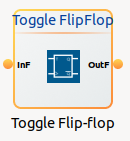
This block is used to find the Toggle Flip-flop of given inputs and store result in the output. On rising edge of the input, toggle the output.
Clock input |
Clock previous state |
Toggle input |
Output |
Edge detected |
|---|---|---|---|---|
Low(0) |
Low(0) |
X (0 or 1) |
Previous state |
No edge triggered |
High(1) |
Low(0) |
0 |
Previous state |
Rising edge |
High(1) |
Low(0) |
1 |
Toggling of Previous state |
Rising edge |
High(1) |
High(1) |
X |
Previous state |
No edge triggered |
Low(0) |
High(1) |
X |
Previous state |
Falling edge |
Name |
Description |
Supported data type |
|---|---|---|
In – Clock Input |
Clock Input |
|
In – Toggle Input |
Toggle Input |
|
Out – Output |
Toggle Flip-flop value of all input values |
Data Flip-flop

This function block performs the logical operation of D FLIPFLOP. Output holds the value it read from Data on the last rising edge of Clock, or 0 if there have been no Clocks since power up. On rising edge of the clock, input value is stored in the output.
Clock input |
Clock previous state |
Data input |
Output |
Edge detected |
|---|---|---|---|---|
Low(0) |
Low(0) |
X (0 or 1) |
Previous state |
No edge triggered |
High(1) |
Low(0) |
0 |
0 |
Rising edge |
High(1) |
Low(0) |
1 |
1 |
Rising edge |
High(1) |
High(1) |
X |
Previous state |
No edge triggered |
Low(0) |
High(1) |
X |
Previous state |
Falling edge |
Name |
Description |
Supported data type |
|---|---|---|
In – Clock Input |
Clock Input |
|
In – Data Input |
Data Input |
|
Out – Output |
Data Flip-flop value of all input values |
Latch

This block is used to Latch of given inputs and store result in the output. While the Latch is False, the Output follows the Input. While the Latch is True, the Output holds the last value it read from Input.When latch is false, input value is stored in the output. Otherwise, output value remains unchanged. If the block is latched from power up, the output will be zero. The Output will be of the same data type as the input.
Output only updates when Enable is high. When Enable is low, the latch “remembers” the previous value (Q_prev).
Enable Latch |
Input |
Output |
Description |
|---|---|---|---|
Low(0) |
X (0 or 1) |
Previous state |
Output holds its previous value. |
High(1) |
Low(0) |
0 |
Output follows input (Input = 0). |
High(1) |
High(1) |
1 |
Output follows input (Input = 1) |
Name |
Description |
Supported data type |
|---|---|---|
In – Latch Input |
Latch Input |
|
In – Data Input |
Data Input |
|
Out – Output |
Latch value of all input values |