CASE STUDY SNAPSHOT
Customer : A leading Indian automotive Tier 1 supplier of instrument clusters and vehicle componentsSize : 1000–10,000
Project vertical : Automotive, Instrument Clusters
Challenge : Design and develop a production-ready commercial vehicle instrument cluster on Renesas RL78 MCU featuring three stepper motor-driven gauges for speed, RPM, and fuel with PID-based needle control and zero-point detection, a segmented LCD display, tell-tale LEDs, and AIS004 Part 3 EMI/EMC compliance
Solution : Production instrument cluster on Renesas RL78 16-bit MCU with 3-axis stepper motor control, PID needle positioning, zero-point detection, 1.9" TN positive segmented display, CAN vehicle bus interface, x15 digital I/O, and AIS004 Part 3 compliant single-layer PCB design
Services & Products Availed : Turnkey Product Engineering, Embedded Hardware Design, Embedded Firmware Development
Tools and Technologies :
- Target MCU: Renesas RL78 (16-bit)
- Display: 1.9" TN Positive Segmented LCD
- Motor Control: 3× Stepper motor, PID controller, Zero-Point Detection (ZPD)
- Vehicle Bus: CAN 2.0
- I/O: x15 Active high/low digital inputs, x3 Resistive inputs
- Indicators: Tell-tale LEDs per ARAI standard
- EMC: AIS004 Part 3
- PCB: Single-layer
- Languages: C
- Tools: Renesas CS+
Introduction
Commercial vehicle instrument clusters, fitted to trucks, buses, tractors, and light commercial vehicles, operate in demanding environments where robustness, accuracy, and regulatory compliance are non-negotiable. Unlike passenger car clusters where graphical TFT displays have become the norm, commercial vehicle clusters in the volume segment continue to rely on proven electromechanical gauge technology, stepper motor-driven needles for speed, RPM, and fuel indication, combined with segmented LCD displays and regulatory-compliant tell-tale indicator arrays.
A leading Indian automotive Tier 1 supplier approached Embien to design and develop a production instrument cluster for a commercial vehicle application on the Renesas RL78 16-bit MCU platform. The cluster had to deliver accurate, responsive gauge indication across three stepper motor-driven parameters, vehicle speed, engine RPM, and fuel level, with a PID-based needle positioning controller and zero-point detection on each axis, a 1.9-inch TN positive segmented LCD for trip and warning information, a full ARAI-standard tell-tale LED array, CAN vehicle bus connectivity, and compliance with AIS004 Part 3 EMI/EMC requirements, all within a cost-optimised single-layer PCB design appropriate for volume commercial vehicle production.
Challenge
The stepper motor control requirement was the most technically demanding aspect of the design. Three independent stepper motors, driving the speed, RPM, and fuel needles, had to be controlled simultaneously, each delivering smooth, accurate needle positioning across their full travel range. Achieving this on a 16-bit RL78 MCU, which has more constrained processing resources than 32-bit automotive MCUs, required a carefully optimised motor control implementation that could service all three axes within the available CPU budget while simultaneously handling CAN message reception, LCD updates, tell-tale management, and diagnostic functions.
Zero-point detection (ZPD) presented a specific challenge for each stepper motor axis. Stepper motors are open-loop devices, they have no inherent knowledge of their current position. On power-up, the needle could be at any position within its travel range, with no direct way for the MCU to know where it is. Without a reliable zero-point detection mechanism, the needle cannot be driven accurately to any target position, as the absolute position reference is unknown. The ZPD algorithm had to reliably establish this reference on each power-up, across the full range of temperatures and mechanical conditions encountered in a commercial vehicle environment.
PID-based needle positioning, rather than simple open-loop step sequencing, was specified to achieve the smooth, automotive-quality needle response that the customer required. Tuning the PID Kp, Ki, and Kd parameters for each axis to deliver the specified rise time, overshoot, and settling behaviour required careful characterisation of the stepper motor and mechanical system dynamics.
The AIS004 Part 3 EMI/EMC compliance requirement imposed constraints on the PCB layout, component selection, and firmware design. Meeting these requirements on a single-layer PCB, where the routing options available to manage EMI are significantly more limited than on a multi-layer board, required particular attention to ground plane management, decoupling capacitor placement, and signal routing discipline.
Solution
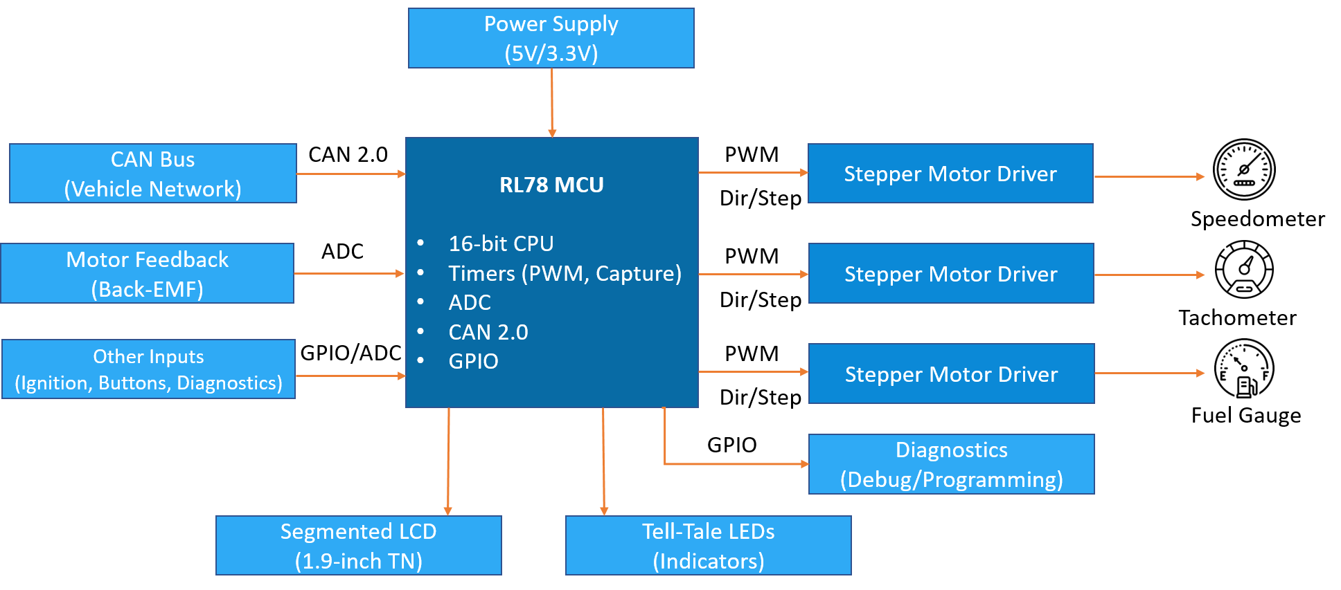
Renesas RL78 Platform and Firmware Architecture
The Renesas RL78 16-bit MCU was selected for its rich peripheral set, including multiple timer channels essential for stepper motor PWM generation, onboard ADC for resistive sensor inputs, CAN controller, and sufficient GPIO for the cluster's digital I/O requirements, at a cost point appropriate for volume commercial vehicle production. The firmware was developed in C using Renesas CS+ development environment, with a task-scheduled architecture that allocated CPU time between stepper motor control, CAN processing, LCD management, tell-tale control, and diagnostic functions in a deterministic, priority-ordered execution structure.
Zero-Point Detection
Zero-point detection was implemented on each of the three stepper motor axes using the RL78's hardware timer capture capability. On power-up, before the prove-out sequence begins, the ZPD routine drives each motor slowly toward its mechanical zero stop. The mechanical stop produces a characteristic change in the motor's back-EMF signature, which is detected by monitoring the motor drive circuit through the RL78's ADC. When the zero stop is detected, the MCU records this position as the axis reference and immediately begins driving the needle toward the zero display position. The ZPD routine handles the full range of starting positions, from a needle resting at zero to one at full-scale deflection, and completes within a time budget consistent with a fast cluster prove-out sequence on ignition-on.
The ZPD algorithm was validated across the operating temperature range specified for the cluster, accounting for the variation in motor electrical characteristics and mechanical friction that temperature introduces. Hysteresis compensation was applied to ensure consistent zero-point detection regardless of the direction from which the needle approaches the mechanical stop.
PID-Based Needle Positioning
Following zero-point detection, each stepper motor axis is controlled by a PID position controller that manages the needle's movement from its current position to the target position demanded by the vehicle data. The PID controller computes the step rate and direction command for each axis at every control cycle, with the Kp, Ki, and Kd parameters tuned independently per axis to reflect the different mechanical characteristics of the speed, RPM, and fuel gauge assemblies.
The PID implementation delivers the smooth, damped needle response characteristic expected of automotive-quality gauges, rising promptly to a new target value without overshoot, settling quickly without oscillation, and tracking smoothly varying inputs such as gradually changing vehicle speed without stepping or jitter. The controller also implements end-stop protection, progressively reducing drive torque as the needle approaches the mechanical travel limits, preventing end-stop impact that would produce an audible click and accelerate mechanical wear.
CAN Vehicle Bus Interface
Vehicle data - speed, RPM, fuel level, engine temperature, and tell-tale status, is received over the CAN 2.0 bus. The CAN reception task maintains a live data table updated on each received message, with timeout monitors detecting loss of any critical message and substituting safe default display values. The CAN database was implemented per the customer's DBC specification, with signal extraction and scaling applied to convert raw CAN data to the physical units required by the gauge control and display functions.
Segmented LCD and Tell-Tale Management
The 1.9-inch TN positive segmented LCD displays trip distance, engine hours, warning codes, and service indicators, the text and numeric information that complements the analogue gauge display in commercial vehicle clusters. The LCD driver was implemented to manage the segment multiplex addressing scheme of the display controller, with a display update task refreshing the LCD content on each change to the displayed data. Tell-tale LEDs, including turn indicators, low battery, high beam, oil pressure, and engine warning, are managed per the ARAI standard indicator definitions, with each tell-tale driven through a GPIO output with appropriate current limiting for the LED specification.
AIS004 Part 3 Compliant PCB Design
The cluster PCB was designed as a single-layer board, a cost-optimised approach appropriate for the volume production context, with the layout discipline required to meet AIS004 Part 3 EMI/EMC compliance. Decoupling capacitors were placed at each power supply pin of the MCU and motor driver ICs. Motor drive lines, the primary source of conducted and radiated emissions in a stepper motor cluster, were routed to minimise loop area and kept physically separated from the CAN and sensor signal traces. Common-mode filtering was applied to the CAN interface lines. The design was validated against AIS004 Part 3 requirements through EMC testing, with any issues identified during testing addressed through component value adjustments and targeted layout modifications within the single-layer constraint.
Benefits
- Simultaneous 3-axis stepper motor control All three gauge axes - speed, RPM, and fuel, controlled concurrently with PID-based positioning on a 16-bit RL78 MCU within a deterministic, multi-function firmware architecture
- Robust zero-point detection Back-EMF based ZPD algorithm validated across the full operating temperature range delivers reliable needle reference establishment on every power-up regardless of starting needle position
- Automotive-quality needle response Independently tuned PID controllers per axis deliver smooth, damped gauge response with end-stop protection across the full operating range
- AIS004 Part 3 compliance Single-layer PCB design meeting Indian automotive EMI/EMC regulatory requirements through disciplined layout practice and targeted filtering, without the cost of a multi-layer board
- Production-ready turnkey delivery Complete hardware and firmware delivered to production standard with full documentation, EMC validation, and CAN DBC implementation per customer specification
Conclusion
This commercial vehicle instrument cluster demonstrates Embien's capability to deliver production-grade automotive cluster products on cost-optimised embedded platforms. By implementing simultaneous three-axis stepper motor control with PID-based positioning and robust zero-point detection on a Renesas RL78 16-bit MCU, while meeting AIS004 Part 3 EMI/EMC requirements on a single-layer PCB, Embien delivered a cluster that combines the accuracy and response quality of premium automotive gauges with the cost structure appropriate for volume commercial vehicle production. This project reflects Embien's deep experience in automotive instrument cluster development across the full range of display and gauge technologies deployed in the Indian and global commercial vehicle market.