
In the world of industrial automation, communication between devices is of utmost importance. One of the most widely used protocols for such communication is Profibus. Profibus, short for Process Field Bus, is a standard for fieldbus communication in automation technology. It is widely used in various industries, including manufacturing, oil and gas, and agriculture, to name a few. The Profibus Fieldbus Data Link Layer (FDL) is the backbone of Profibus, enabling reliable and efficient fieldbus communication between devices on the industrial fieldbus network. In this comprehensive guide, in continuation of our earlier article, we will delve deep into the workings of the Profibus Fieldbus Data Link Layer and unravel the features and technology behind this critical protocol layer.
Layer 2 of the Profibus Fieldbus Data Link Layer provides a reliable channel for fieldbus communication between the higher application layer and other nodes in the bus. The Profibus Fieldbus Data Link Layer is internally organized as below:

Profibus FDL - Fieldbus Data Link Layer
Fieldbus Link Control (FLC) is responsible for receiving the data transmission services and passing them on to the MAC. Media Access Control (MAC) implements the complete bus access management according to the underlying physical layer. The Fieldbus Management (FMA) provides the management services to the higher application layer.
The data transmission services, as the name implies, are primarily for the fieldbus communication of data between the nodes. Many services are offered such as Send Data with Acknowledge (SDA), Send Data with No Acknowledge (SDN) etc., which will be covered later. These are provided via the FLC.
The management services offered by the Fieldbus Management are for operational management of the node such as:
With these services, it is possible to implement a complete process control node. Embedding a full Profibus Fieldbus Data Link Layer stack in controller hardware requires purpose-built embedded computing platforms that provide the real-time performance and I/O flexibility demanded by industrial fieldbus network deployments.
As we have seen earlier, the Profibus Fieldbus Data Link Layer operates as a master-slave protocol where fieldbus communication takes place between master and slave devices on the industrial fieldbus network. The master device is typically an active node such as a PLC, PC, or control system that initiates the fieldbus communication and controls the data exchange process while it is holding the token. The slave devices are passive peripherals such as field devices, drives, IO controllers, and transmitters, which respond to requests from the master and provide the necessary information. The slave station never owns tokens and hence cannot initiate requests on the bus.
A simple industrial fieldbus network with one master and 3 slaves will look as follows:

Profibus Example Network
While we will explore the concepts of DP-Master and DP-Slaves a little later, it is possible that there can be more than one master in the system. The masters will pass tokens between them to determine who owns the bus currently, thereby forming a logical ring-like structure.
Each of the stations in the Profibus FDL network must be uniquely identifiable and hence are given an 8-bit address. The addresses are preconfigured during the setup phase and cannot be changed dynamically over the course of operation. The addresses defined within the Profibus FDL are:
| Address | Usage |
|---|---|
| 0 | Reserved for diagnostic tools |
| 1 to N | Master station addresses as masters should be in the lower addresses |
| N to 125 | Slave station addresses |
| 126 | Used to deliver dynamically set address |
| 127 | Broadcast address |
Thus, it is possible to connect up to 125 nodes in a Profibus Fieldbus Data Link Layer network.
Now let us familiarize ourselves with the Profibus frame format as defined by the Profibus FDL. Referred to as telegrams, the frames are of pre-defined structures and are of 5 types.
The frame formats for these telegrams looks like as follows:

Profibus Telegram Frame Format
The description of the telegram fields is given below:
| Field | Size | Description |
|---|---|---|
| SD | 1 | Start Delimiter |
| DA | 1 | Destination Address |
| SA | 1 | Source Address |
| FC | 1 | Function code indicating the telegram type |
| LE | 1 | Length of the telegram including DA, SA, FC and PDU |
| LEr | 1 | Repetition of LE. For redundancy with hamming distance of 4 |
| PDU | Variable | Protocol Data Unit |
| FCS | 1 | Frame Checking Sequence for error check |
| ED | 1 | End Delimiter |
The underlying physical layer transmits the data as per the electrical characteristics of the communication medium and ensures reliable Profibus data transmission.
The Profibus Fieldbus Data Link Layer handles the framing and error checking of the data packets. Each byte of the telegram is transmitted in 8E1 configuration where it has 8 data bits, one even parity bit with 1 stop bit. The integrity of the transmitted data is ensured through the FCS byte.
To better understand the fieldbus communication of telegrams on the physical bus, let us see how it works in practice.
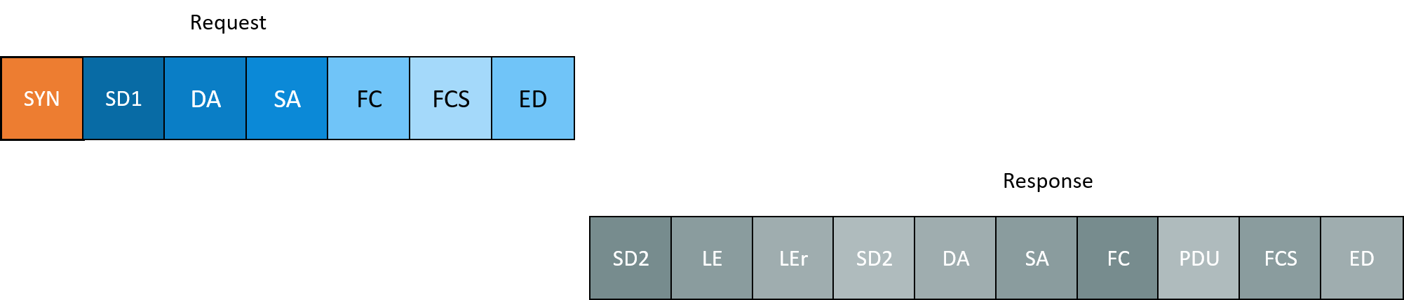
Profibus Telegram Communication Sequence
The blue-colored packets represent the data originating from the master and gray-colored ones represent the data transmitted by the slave. The SYN is at least 33 bits of logical ones, i.e. bus in idle condition, and represents the start of a new telegram.
Another important aspect of the Profibus FDL Medium Access Protocol is the token passing procedure. The token represents the right to transmit data on the industrial fieldbus network. In a token passing system, only the device holding the token has the authority to send data.
The token passing procedure ensures fair and efficient access to the network. It prevents collisions and ensures that each device gets an equal opportunity to transmit its data. When a master wants to transmit data, it waits for the token to be passed to it. Once it receives the token, it can transmit its data and then passes the token to the next master in the network. The bus configuration dictates a Token Rotation time, by which the token must have completed one rotation of the logical ring. Generally, if any master receives a token, it checks if there is some time left. Only then is the data transmitted; otherwise it will be passed on to the next master hoping to transfer in the next rotation.
Profibus DP (Decentralized Periphery) is a variant of PROFIBUS that is widely used in distributed control systems and relies on the Profibus Fieldbus Data Link Layer for its underlying fieldbus communication. It allows for the connection of multiple devices in a decentralized manner, improving the flexibility and scalability of the industrial fieldbus network. Based on the need, there are 3 communication profiles specified, each offering a variable level of performance.

Profibus Performance Levels
DP-V0is the lowest performance level that offers basic DP functionality such as cyclic data exchange, station, module, and channel diagnostics.
DP-V1,optimized for process automation, also offers acyclic data exchange and alarm features.
DP-V2is primarily optimized for drive technology and offers slave-to-slave communication.
The higher profiles offer rich configuration features with support for IEC 61131-3 PLC blocks, GSD based configuration, etc.
The Profibus Fieldbus Data Link Layer supports 3 classes of devices.
PROFIBUS DP master (class 1):It uses cyclical fieldbus communication to exchange process data with its associated slaves. Typically available in a memory programmable controller or an automation station of the process control system.
PROFIBUS DP master (class 2):It can be used to set device parameters via acyclical communication. Typically they are part of engineering stations used for device configuration.
PROFIBUS slave:Passive communication devices that respond to requests from the masters. Some devices that implement this include I/O controllers, drives, valves, transducers, and analyzers.
The Profibus slave needs to be configured before starting operation. The below state diagram captures the states of a slave on starting up.

Post power on, the devices wait for Parameter data to be received from the master. After that it moves to a Wait for Configuration state where it receives the configuration data from the master. On successful reception and configuration of the same, it moves on to the data exchange state.
As discussed earlier, the Profibus Fieldbus Data Link Layer primarily works in a cyclic mode of operation. Called MS0, in this mode the masters poll the slaves cyclically one after another. Once the cycle is over, it restarts the polling from the first slave again.
Sometimes there is a need for acyclic fieldbus communication. It can be achieved using MS1 or MS2 links. MS1 link can be set up by a DPM1 master as a connection-oriented link after configuration of the slave. Each slave can have only one MS1 link active at a time. The MS2 link is set up by a DPM2 master with the slave, where a slave can have more than one active MS2 links with different masters. Each MS2 link is governed by its own timing parameters and mechanisms.
With a good understanding of the Profibus Fieldbus Data Link Layer, now let us have a brief look at the Profibus data transmission services offered. The services offered are listed below:
| Service | Function | DP-V0 | DP-V1 | DP-V2 | FMS | Usage |
|---|---|---|---|---|---|---|
| SDN | Send Data with No acknowledge | X | X | X | X | Primarily for broadcast purposes |
| SDA | Send Data with Acknowledge | X | X | Point to point communication with no data and the slave acknowledges | ||
| SRD | Send and Request Data | X | X | X | X | To read data from passive node where the recipient may or may not respond with data based on availability |
| CSRD | Cyclic Send and Request Data | X | To transfer data cyclically to remote stations | |||
| MSRD | Send and Request Data with Multicast Reply | X | Like SRD, here the response is consumed by more than one recipient. | |||
| CS | Clock Synchronization | X | X | Used for clock synchronization services by the DP-V2 master |
It is essential for every Profibus device to support one or more of these Profibus data transmission services. Teams building or porting Profibus data transmission stacks for embedded controllers will find that purpose-built industrial automation services can accelerate development, certification, and deployment of Profibus FDL implementations across diverse industrial fieldbus network environments. The reliability of PROFIBUS data link communication makes it well suited for integration with modern IoT gateways across multiple industrial domains.
The Profibus Fieldbus Data Link Layer provides the reliable transport backbone of any industrial fieldbus network, governing token passing, telegram framing, station addressing, and master-slave fieldbus communication across DP and FMS profiles. Understanding the Profibus FDL is essential for engineers developing or integrating Profibus devices, as its Profibus data transmission services and addressing mechanisms underpin every exchange on the network — from simple cyclic polling to complex acyclic configuration and alarm handling.
Ruggedized embedded computing platforms optimized for industrial fieldbus applications, supporting Profibus FDL stacks and real-time data link layer implementations.

End-to-end industrial automation services encompassing Profibus FDL integration, master-slave configuration, and cyclic data exchange for factory and process control systems.
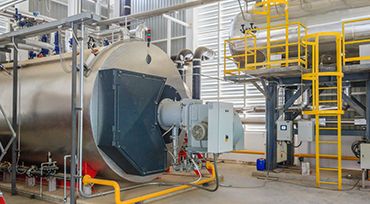
A case study on developing a boiler monitoring system with a commercial off-the-shelf Android HMI for real-time industrial process visibility.