
The Modbus Protocol is a widely used industrial communication standard that has revolutionized the way devices in the industrial automation sector communicate with each other. Developed by Modicon in 1979, the Modbus Protocol has become the de facto standard for connecting a wide range of devices, including sensors, actuators, and controllers, in industries such as manufacturing, energy, and transportation. Though this protocol is extensively covered by countless articles, this page will serve as a basis of upcoming articles on various other industrial protocols.
The Modbus Protocol is a simple client-server protocol that operates with limited computing resources, making it versatile and adaptable to various communication mediums. It offers a simple and efficient way to exchange data between devices, enabling seamless integration of different systems within an industrial environment. As a foundational industrial automation protocol, Modbus continues to serve as the backbone of SCADA communication systems and distributed control architectures across the globe.
To understand how the Modbus Protocol works, it is essential to examine its mapping to the OSI model.
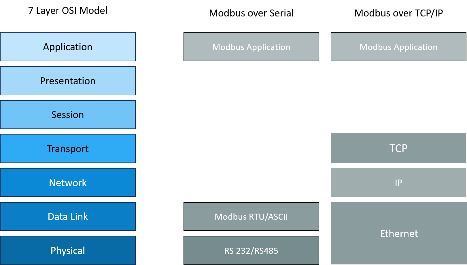
The Modbus application protocol operates at the application layer (Layer 7) and the data link layer (Layer 2) of the OSI model.
At the application layer, Modbus defines a set of function codes that determine the type of operation to be performed on the data exchanged between devices. These function codes provide a standardized way of controlling and monitoring devices in an industrial setting.
For serial communication, at the data link layer, the Modbus Protocol utilizes a simple frame format to encapsulate the data being transmitted. This frame format consists of various fields, including the address field, function code field, data field, and error checking field.
For TCP/IP interfaces, as the transport channel itself is reliable, no additional CRCs are used.
The Modbus Protocol defines a Protocol Data Unit (PDU) that is common to all underlying transport channels and an Application Data Unit (ADU) that is specific to the channels. The frame format of the Modbus PDU contains only two fields as shown below.

The function code field specifies the type of operation to be performed on the data. It can indicate read or write operations.
The data field contains the actual data being transmitted between devices. It can vary in size depending on the specific function code and application requirements.
The Modbus Protocol defines several function codes that serve different purposes in industrial communication. These function codes allow devices to request data, write data, perform diagnostics, and more.
Some commonly used function codes include:
| Function Code | Name | Description |
|---|---|---|
| 0 | 0 | No address information is present |
| 1 | Read Coils | Read the status of discrete coils in a device |
| 2 | Read Discrete Inputs | Read the status of input registers in a device |
| 3 | Read Multiple Registers | Read the status of multiple holding registers in a device |
| 16 | Write Multiple Registers | Write a series of holding registers in a device |
| 4 | Read Input Registers | Read the status of multiple input registers in a device |
| 5 | Write Single Coil | Write a single coil in a device |
| 6 | Write Single Register | Write a single register in a device |
| 7 | Read Exception Status | Read information about the last exception |
| 15 | Write Multiple Coils | Can be used to set multiple coil values in a single go |
| 20 | Read File Record | Read a file record information |
| 21 | Write File Record | Write a file record information |
| 22 | Mask Write Register | Write a holding register after applying AND & OR masks |
| 23 | Read/Write Multiple Registers | Performs a write after read operation |
| 24 | Read FIFO | Reads from the device FIFO |
| 43 | Read Device Information | Fetch information about the device including vendor name, product code, versions etc. |
Coils represent actuators in the form of relays and registers are more precise multi-bit sensor information like levels. Holding registers are typical read/write while input registers are read only. These function codes provide a standardized way of interacting with devices, ensuring interoperability and ease of implementation in industrial systems. In addition to these, there are codes reserved for proprietary uses.
Based on the function codes, the data frame varies. For example, for the read input register PDU request frame format looks like the below table.
| Field | Value | Description |
|---|---|---|
| Function Code | 02 | Indicates read input status |
| Register Address | Starting Address Hi | MSB of register address |
| Starting Address Lo | LSB of register address | |
| Number of Points to read | Number of Points Hi | MSB of register count |
| Number of Points Hi | LSB of register count |
Based on the function codes, the data frame varies. For example, for the read input register PDU request frame format looks like below table.
| Field | Value | Description |
|---|---|---|
| Function Code | 02 | Indicates read input status |
| Byte Count | Number of Bytes | Response Data length |
| Data Value | Value byte 1 | MSB of first register value |
| Value byte 2 | MSB of first register value | |
| Value byte n | LSB of last register address |
The address value ranges from 0x0 to 0xFFFF, and there are conventions to represent coils from address 00001 to 09999, discrete inputs from 10001 to 19999, input registers from 30001 to 39999 and holding registers from 40001 to 49999.
In any communication protocol, the possibility of errors exists. The Modbus Protocol defines specific error codes to indicate various error conditions that may occur during communication. Some common Modbus error codes include:
| Error Code | Error Name | Description |
|---|---|---|
| 1 | Illegal Function | Unsupported function code |
| 2 | Illegal Data Address | Invalid address requested for |
| 3 | Illegal Data Value | Invalid value provided for data |
| 4 | Server Device Failure | Some error occurred when attempting operation |
| 5 | Acknowledge | Command accepted |
| 6 | Server Device Busy | Device busy. Client to try again later |
| 7 | Negative Acknowledge | Unable to perform operation |
| 8 | Memory Parity Error | Parity error detected |
| 10 | Gateway Path Unavailable | Gateway is not configured |
| 11 | Gateway Target Device Failed to Respond | Gateway is unable to reach target device |
Understanding these error codes is essential for troubleshooting and diagnosing communication issues in Modbus-based systems.
Modbus RTU (Remote Terminal Unit) is a binary representation of the Modbus Protocol. It uses binary data encoding and is the most commonly used format in industrial applications. Modbus RTU offers faster transmission speeds and higher data throughput compared to Modbus ASCII, making it the preferred choice for most industrial automation deployments.
A Modbus RTU network over the serial RS485 line looks like as depicted below:
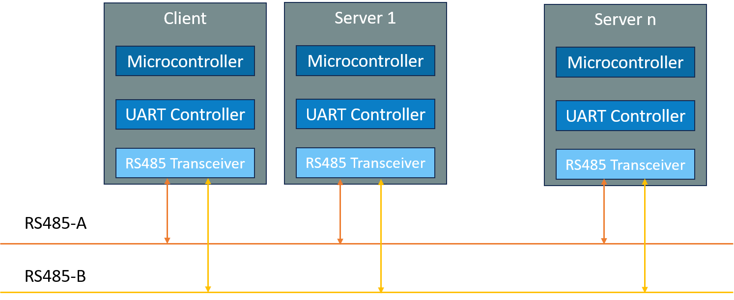
As it can be seen, being a client-server protocol, there are more than one server which one client communicates with. The APDU for the serial Modbus RTU is as below:

The Modbus RTU ADU can span a maximum of 256 bytes.
The address field indicates the device or group of devices involved in the communication. It allows for the identification of the sender and the recipient of the data.
The error checking field, also known as the CRC field, ensures data integrity during Modbus RTU transmission. It allows the recipient to verify the accuracy of the received data and detect any errors that may have occurred. The CRC is calculated using the CRC-16-MODBUS with its polynomial value being x16 + x15 + x2 + 1, i.e. 0x8005.
There are two time periods that are to be carefully taken care during the implementation. The inter-character timeout, i.e. time between two consecutive characters being transferred, must not be more than 1.5 times the character transfer time. And the inter-frame timeout, the time interval between two frames, must be at least 3.5-character transmission time. Assuming the Modbus RTU line operates at a speed of 9600 bauds per second with 8N1 configuration, each character occupies a bus time of 1.04 ms. So, the inter-character time is 1.56 ms and inter-frame timeout is 3.64 ms.
Modbus ASCII (American Standard Code for Information Interchange) is a human-readable representation of the Modbus Protocol. It uses ASCII characters to encode data and uses a different checksum called LRC for validation. Modbus ASCII is slower compared to Modbus RTU due to the overhead of converting data to ASCII characters.
Engineers integrating Modbus RTU into production systems can benefit from Embien's product engineering services, which cover protocol stack development, hardware-software integration, and field validation for industrial deployments.
Modbus TCP is another widely used implementation of the Modbus Protocol. It allows devices to communicate over Ethernet networks, enabling seamless integration with existing IT infrastructure. Modbus TCP operates at the application layer of the TCP/IP stack and utilizes the same function codes as the serial versions of the Modbus Protocol. It offers advantages such as faster data transmission, support for larger data payloads, and the ability to communicate over long distances. The server supports the protocol over TCP port 502 to which the client can connect and communicate.
The ADU of the Modbus TCP protocol is as follows:
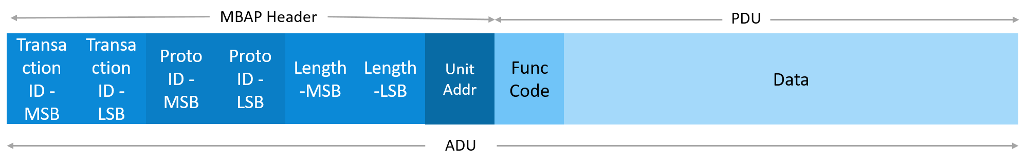
Modbus TCP introduces a Modbus Application header that has 4 fields:
Since TCP itself is quite reliable, there is no need for additional CRCs. The maximum Modbus TCP ADU size is fixed to 260 bytes.
Modbus TCP is widely adopted in modern industrial systems due to its compatibility with Ethernet networks and its ability to leverage existing networking infrastructure. Teams deploying Modbus TCP in factory environments often rely on industrial automation services for end-to-end network design, device commissioning, and SCADA integration.
Like any communication protocol, the Modbus Protocol has its advantages and disadvantages. Understanding these can help in making informed decisions when implementing industrial communication systems.
Advantages of the Modbus Protocol include:
Simplicity: Modbus is easy to learn and implement, making it accessible to a wide range of usersDisadvantages of the Modbus Protocol include:
Limited Security: Modbus lacks built-in security features, making it vulnerable to unauthorized access and data breachesDespite being developed over four decades ago, the Modbus Protocol continues to be widely used in industrial automation. However, as technology advances and new communication protocols emerge, the future of Modbus remains an open question.
The introduction of newer protocols, such as OPC-UA and MQTT, has challenged the dominance of the Modbus Protocol in the industrial communication landscape. These protocols offer advanced features, improved security, and better support for IoT applications. The Modbus Protocol proposes to use TLS security over port 802 to support a cyber-secure version of the Modbus TCP implementation.
However, due to its widespread adoption and compatibility with legacy systems, the Modbus Protocol is expected to remain relevant in the industry for the foreseeable future. The ongoing development of gateways and converters also allows Modbus devices to integrate with modern IoT platforms, ensuring its continued use as a foundational industrial automation protocol across factory, energy, and transportation environments. SCADA communication systems in particular continue to rely heavily on Modbus connectivity for data acquisition from field devices. Embien’s digital transformation and predictive maintenance services leverage Modbus-connected assets to unlock operational insights and improve reliability.
The Modbus Protocol remains a cornerstone industrial automation protocol, connecting sensors, actuators, and controllers across manufacturing, energy, and transportation sectors with proven simplicity and reliability. Both Modbus RTU for serial deployments and Modbus TCP for Ethernet-based SCADA communication environments remain deeply embedded in industrial infrastructure worldwide, and their continued relevance underscores the protocol's enduring value in distributed control systems.

End-to-end product engineering support for industrial communication systems, from protocol stack development to hardware integration and validation.

Comprehensive industrial automation services covering fieldbus integration, PLC interfacing, SCADA connectivity, and factory modernization solutions.

A case study on developing an industrial-grade Modbus RTU to cloud gateway with IP40 enclosure for remote monitoring and data acquisition.