
In a conventional internal combustion vehicle, the 12V electrical system distributes power from a battery through fuses and relays to every consumer in the vehicle. The architecture is straightforward, low voltage, low energy density, and forgiving of connection and disconnection events.
Electric vehicles operate on a fundamentally different premise. The traction battery pack operates at 400V or 800V, stores tens of kilowatt-hours of energy, and is connected to motor inverters, DC-DC converters, and HVAC compressors that each draw continuous currents measured in hundreds of amperes. A fault in this high-voltage (HV) system, an insulation breakdown, a contactor weld, a precharge failure, can result in catastrophic fire or electrocution of service personnel and first responders.
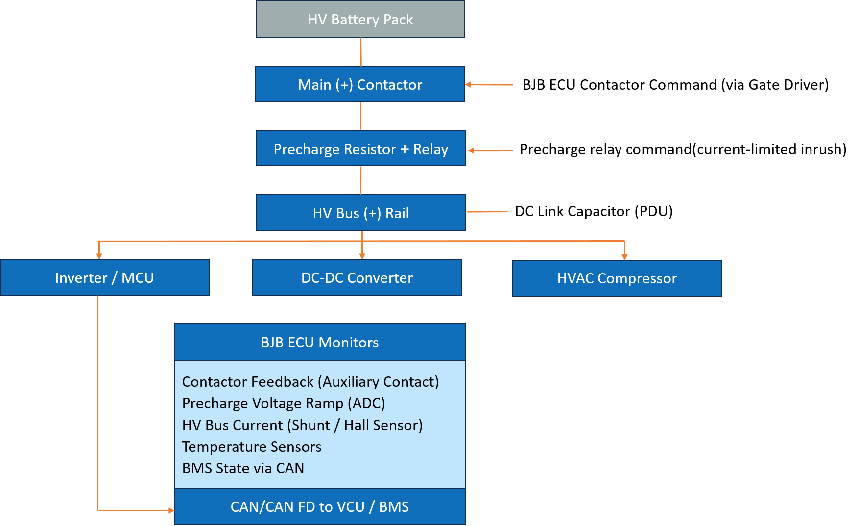
The Battery Junction Box (BJB) is the HV system's primary control and protection node. It houses the main contactors that physically connect and disconnect the battery pack from the vehicle's HV bus, the precharge circuit that safely charges the DC link capacitors before the main contactors close, the insulation monitoring device, current sensors, and the fusing that protects against overcurrent. The ECU embedded within or alongside the BJB controls all of these functions, monitors the HV system's health continuously, and coordinates with the Battery Management System (BMS) and Vehicle Control Unit (VCU) to manage HV system state transitions safely.
This article examines the BJB ECU's architecture, hardware design, software structure, and the ASIL-D safety requirements that govern its most critical functions.
The BJB ECU manages the complete lifecycle of the HV system's power state, from the initial power-on sequence through normal operation to controlled shutdown and emergency disconnection.
| Input | Description |
|---|---|
| BMS state and permission signal | CAN message authorising HV activation from the BMS |
| VCU ignition / ready signal | System-level wake and ready signal from VCU |
| Contactor auxiliary contacts | Hardware feedback confirming contactor open/closed state |
| Precharge voltage measurement | ADC input monitoring HV bus voltage during precharge ramp |
| HV bus current | Shunt resistor or Hall-effect sensor measuring HV bus current |
| Insulation monitoring result | IMD device output - insulation resistance of HV to chassis |
| Temperature sensors | NTC thermistors monitoring contactor and busbar temperature |
| Output | Description |
|---|---|
| Main (+) contactor command | Gate driver signal closing/opening positive main contactor |
| Main (-) contactor command | Gate driver signal closing/opening negative main contactor |
| Precharge relay command | Signal controlling precharge resistor bypass relay |
| Cooling request | Thermal management request to thermal management ECU |
| Status and fault to VCU/BMS | CAN messages reporting HV state, faults, and diagnostics |
| Emergency disconnect command | Hardware-direct contactor open on critical fault |
| Mode | Description |
|---|---|
| Standby | HV system disconnected, BJB ECU powered from 12V LV system, monitoring IMD |
| Precharge | Precharge relay closed, monitoring voltage ramp across DC link capacitors |
| HV Active | Main contactors closed, HV bus energised, continuous monitoring active |
| Discharge | Controlled ramp-down before contactor opening |
| Emergency Disconnect | Immediate contactor opening on critical fault - hardware-enforced |
| Diagnostic | UDS diagnostics via CAN - DTC readout, contactor actuation test, EOL |
Governing Standards: ISO 26262 at ASIL D applies to the contactor control and emergency disconnect functions. ISO 6469 governs EV safety, defining insulation resistance requirements, connector interlock requirements, and service disconnect provisions. FMVSS 305 (US) and ECE R100 (Europe) define HV system safety requirements for production vehicles.
Microcontroller
The ASIL D requirements on contactor control demand a lockstep dual-core MCU. The Infineon AURIX TC2xx/TC3xx series and NXP MPC5748G are the dominant choices in production BJB ECUs. Both provide dual-core lockstep with cycle-accurate hardware comparison, integrated high-side driver outputs for contactor gate drive, and CAN FD controllers for BMS/VCU communication.
The MCU must manage two functionally independent channels for the emergency disconnect function, one software-commanded, one hardware-direct, to satisfy the ASIL D single-point fault metric requirements. The hardware-direct path operates independently of software: if the watchdog expires or the MCU detects an internal lockstep error, the hardware path forces the contactor coil drivers to their safe (open) state without software intervention. Robust embedded hardware design is critical for reliable contactor control, power distribution, sensing, and protection in high-voltage EV systems.
Memory
Flash: 4–8 MB for program code, contactor control calibration tables, and bootloader. The bootloader must be ASIL D qualified and implement secure boot to prevent unauthorised firmware modifications.
RAM: 512 KB–1 MB for real-time monitoring variables, fault state machines, and CAN message buffers.
Data Flash stores DTCs, contactor actuation counts (contactors have limited mechanical lifetimes, typically 100,000 to 300,000 operations), and calibration constants.
Communication Interfaces
CAN FD is the primary vehicle interface, receiving BMS permission signals and VCU commands, transmitting HV state, fault status, and sensor data.
The BJB typically implements two CAN channels: one for BMS coordination (often a dedicated, high-priority safety CAN bus) and one for general vehicle network participation. Baud rates of 500 kbps (CAN) or 2 Mbps (CAN FD) are typical.
HV Interface Hardware
The contactor coil drivers are the BJB ECU's most critical hardware outputs. Contactors are electromagnetic relays, their coils require 12V at several amperes to close and hold. The BJB ECU drives these coils through high-side/low-side driver ICs with integrated diagnostics: open-load detection (coil wire break), overcurrent detection, and actual current feedback. This feedback is essential for distinguishing a commanded open from a welded contactor, a contactor that has fused closed due to an overcurrent event is one of the most dangerous BJB failure modes.
The precharge circuit consists of a resistor (typically 20–100 ohm, rated for the inrush energy) in series with a relay. The precharge sequence: close the precharge relay, monitor the HV bus voltage via ADC as it rises to match battery voltage, then close the main contactors and open the precharge relay. The ADC monitoring must detect a failed precharge resistor (no voltage rise), a failed precharge relay (no current flow), and a short circuit on the HV bus (voltage not rising despite current flowing) within the precharge timeout window.
Insulation Monitoring Device (IMD)
The IMD continuously measures the insulation resistance between the HV bus (both positive and negative rails) and the vehicle chassis. ISO 6469 requires a minimum of 100 ohm/V, for a 400V system, this means a minimum insulation resistance of 40 kohm. A degraded insulation reading below this threshold triggers a fault and, depending on the severity, either a warning or an emergency HV disconnect. The IMD injects a low-level AC or DC test signal onto the HV bus and measures the return current to compute insulation resistance. This must operate correctly whether the HV system is energised or in standby.
AUTOSAR Classic - Essential for ASIL D
BJB ECU software runs on AUTOSAR Classic universally. The ASIL D requirements, deterministic control cycle requirements, and the need for pre-qualified BSW (particularly the watchdog manager and diagnostic event manager) make Classic the only practical choice.
| BSW Module | Role in BJB ECU |
|---|---|
| AUTOSAR OS | Fixed-priority scheduling - 10 ms control cycle at highest priority |
| CAN Driver / Com | BMS permission receive, VCU command receive, status transmit |
| ADC Driver | Precharge voltage monitoring, temperature sensor reading |
| IoHwAb | Contactor driver command abstraction |
| WdgManager | Dual watchdog supervision - triggers hardware contactor open on miss | DiagEventManager | DTC management - contactor weld, IMD fault, precharge failure |
| DCM | UDS diagnostics - DTC readout, contactor actuation routine, live data |
| EcuM | Power state management - LV wake to HV active sequencing |
Application Software Components
HV State Machine SWC: The central controller of the BJB ECU. Implements the state machine governing transitions between Standby, Precharge, HV Active, Discharge, and Emergency Disconnect states. State transitions are permitted only when all entry conditions are met, BMS permission received, IMD resistance above threshold, contactor auxiliary feedback consistent with commanded state, precharge voltage within tolerance. Any condition violated outside the expected window triggers a fault state transition.
Contactor Control SWC: Drives the contactor coil drivers based on state machine commands. Implements the coil energisation sequence, controlled coil current ramp to reduce EMI from relay switching, and monitors driver feedback for open-load and short-circuit conditions. Maintains contactor actuation count in NvM for lifetime monitoring.
Precharge Management SWC: Executes the precharge sequence. Monitors the ADC voltage ramp against a timeout window calibrated for the expected RC time constant of the precharge resistor and HV bus capacitance. Detects failed precharge (no ramp), short circuit (ramp too slow despite current), and precharge relay weld (voltage present with relay commanded open).
IMD Supervision SWC: Reads insulation resistance from the IMD device (via CAN or a dedicated digital interface), compares against the ISO 6469 threshold, and triggers the appropriate fault response. Implements a debounce to prevent nuisance faults from transient IMD readings during HV bus switching events.
Thermal Monitoring SWC: Reads NTC thermistor temperatures from contactor bodies and HV busbars. Applies derating, reducing the permitted continuous current or duty cycle, when temperatures approach limits. Triggers emergency disconnect if thermal limits are exceeded.
ASIL Rating: The contactor control and emergency disconnect functions are ASIL D, the hazard of an uncontrolled HV bus connection or inability to disconnect in an emergency carries maximum severity (electrocution, fire), high exposure, and minimal controllability. ASIL decomposition is applied: the software command path is one ASIL B(D) channel; the hardware-direct watchdog-triggered open path is the second ASIL B(D) channel.
Contactor Weld Detection: A welded contactor is an ASIL D safety goal violation, the vehicle cannot disconnect from the HV source. Detection uses the auxiliary contact feedback: if the auxiliary contact indicates the contactor is closed when the ECU has commanded it open, a contactor weld is declared. This must be detected within one control cycle. The HV system must be flagged as inoperable and the vehicle must not allow restart until the fault is resolved.
ISO 21434 Relevance: The CAN interface receiving BMS permission signals is a credible attack surface, a spoofed BMS permission signal could cause unintended HV activation. SecOC authentication on the BMS-BJB permission interface is the standard mitigation on connected vehicle platforms.
BJB functionality is increasingly being integrated into the Battery Management System hardware, combining the contactor control ECU, cell monitoring electronics, and communication gateway into a single high-voltage module inside the battery pack. This reduces external wiring, improves thermal management, and simplifies the vehicle's HV architecture.
Solid-state contactors, using power semiconductors (SiC MOSFETs) rather than mechanical relay contacts, are emerging as an alternative to electromechanical contactors. They eliminate the contactor weld failure mode, extend cycle life dramatically, and enable faster switching for more sophisticated HV management strategies. The ECU architecture remains similar but the gate drive interface and diagnostics change significantly.
Embien has experience in developing ASIL D compliant embedded software for powertrain and HV management ECUs, including contactor state machines, AUTOSAR Classic BSW configuration, and CAN FD communication stacks for safety-critical applications. Our teams have worked with Infineon AURIX and NXP MPC57xx platforms in ASIL D programs and are familiar with the ISO 26262 documentation, FMEDA, and verification evidence requirements for HV system safety functions. We have supported BMS and HV system integration programs for EV customers across automotive and commercial vehicle domains.
To discuss your BJB ECU or HV system embedded development requirements, reach out to the Embien team.

End-to-end product engineering expertise for developing safety-critical EV control units, power electronics, and high-voltage system architectures.

Specialized automotive engineering expertise for developing high-voltage power distribution, battery management, and safety-critical ECU systems.

A case study on developing an AIS 140-certified 4G CAN data logger that enables reliable vehicle monitoring, offline data storage, cloud connectivity, and FOTA/COTA updates for commercial fleet applications