
For most of automotive history, headlights were a binary proposition, on or off, low beam or high beam. The beam pattern was fixed by the physical geometry of the reflector and lens, aimed once at the factory, and left unchanged regardless of whether the vehicle was cornering sharply at low speed, cruising a straight motorway at 130 km/h, or navigating rain-soaked city streets at night.
The consequences of this simplicity are well understood. Drivers switch to low beam when oncoming traffic appears, sacrificing up to 60% of their forward visibility range in the process. Fixed beam patterns cannot follow road curvature into a bend. Rain and fog call for entirely different light distributions that fixed beams cannot provide.
The Advanced Front Lighting System (AFS) addresses these limitations by making the headlight beam dynamically adaptive, swivelling the beam to follow road curvature, adjusting beam range with vehicle speed, and switching between optimised patterns for different driving conditions. Its most advanced expression, the Adaptive Driving Beam (ADB) or matrix LED high beam, goes further still: using individually controlled LED segments to maintain full high-beam illumination of the road while simultaneously masking the exact position of oncoming vehicles and pedestrians, eliminating glare without sacrificing visibility.
The ECU that orchestrates all of this, receiving camera data, vehicle dynamics signals, and ambient conditions, then driving LED current controllers and swivel actuators in real time, is the subject of this article.
The AFS ECU manages the complete adaptive behaviour of the front lighting system. In its full ADB implementation, it combines mechanical beam aiming (swivel and levelling actuators) with electronic beam shaping (matrix LED pixel control) to produce a continuously optimised light distribution for every driving situation.
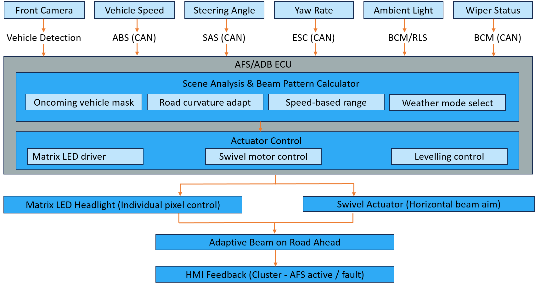
Key Inputs:
Key Outputs:
| Mode | Description |
|---|---|
| City Mode | Wide, short-range beam - low speed urban environment |
| Country Mode | Standard asymmetric low beam - rural roads |
| Motorway Mode | Narrow, long-range high beam - sustained high speed |
| Cornering Mode | Beam swivelled toward direction of travel |
| Adverse Weather | Flat, wide beam reducing backscatter in rain/fog |
| ADB / Glare-Free High Beam | Full high beam with dynamic masking of oncoming vehicles |
| Static Levelling | Beam aim corrected for vehicle load / pitch |
| Fault / Degraded | Fault detected - fixed low beam fallback |
Governing Standards: ECE Regulation 123 (ECE R123) governs AFS systems for passenger vehicles in markets following UN regulations, defining beam pattern requirements, swivel limits, and failure behaviour. FMVSS 108 governs lighting in the United States. ECE R149 specifically covers ADB (matrix high beam) systems, defining the masking performance requirements for oncoming vehicle glare prevention. ISO 26262 applies, AFS lighting failure is typically rated ASIL A to ASIL B depending on the specific safety goal analysis.
Microcontroller
AFS ECU computational demands are moderate compared to chassis safety ECUs, the primary tasks are camera data processing for object position extraction, beam pattern calculation, actuator control loop execution, and LIN bus communication management. This places the AFS ECU firmly in the domain of mid-range automotive MCUs.
The Renesas RA6 series, NXP S32K1xx, and STMicroelectronics SPC5 families are typical choices. These provide sufficient processing capability (Cortex-M4/M7 cores at 120–240 MHz) for the AFS control tasks with a peripheral set well matched to the LIN, SPI, and PWM interfaces the system requires. Where the AFS function is integrated into a broader body domain controller, the host MCU may be a more capable device shared with BCM functions.
For ADB systems receiving processed object data from a dedicated camera or ADAS ECU over Ethernet, an additional Ethernet MAC peripheral is required, available on higher-end variants of the S32K and RA families, or handled through an external Ethernet controller.
Memory
Flash: 1–2 MB for AFS program code. Beam pattern lookup tables, defining LED segment states for each combination of mode, speed, and object position, are the largest data consumers and occupy a significant portion of calibration flash
RAM: 128–512 KB for control loop variables, camera object buffers, and LED state arrays
Data Flash: DTC storage, EOL calibration results (swivel zero position, levelling reference angle), and operating hour counters for LED lifetime monitoring
Communication Interfaces
CAN FD (primary): Engine torque requests to ECM, brake pressure coordination with ESC HCU, status to cluster. High-priority messages, torque reduction requests, are allocated the shortest CAN arbitration IDs to minimise bus latency
LIN (primary actuator bus): The dominant interface for AFS because LIN's low cost and adequate bandwidth suit the headlight module's actuator and driver IC communication needs. A dedicated LIN master on the AFS ECU drives the headlight module's LED driver ICs, swivel motor controller, and levelling motor controller. LIN's 20 kbps bandwidth is sufficient for the LED segment update rate (typically 50–100 Hz) and actuator position commands
CAN / CAN FD (vehicle bus): Receives vehicle speed, steering angle, yaw rate, and BCM status. Transmits AFS status and fault information
Automotive Ethernet (100BASE-T1): Used on integrated platforms where the AFS ECU receives pre-processed object detection data (oncoming vehicle bounding boxes) from the ADAS fusion ECU or a dedicated surround-view camera system
SPI (internal): Direct interface to LED driver ICs in some designs where the driver IC is mounted on the AFS ECU board rather than inside the headlight module
LED Driver Architecture
Matrix LED headlights use dedicated LED driver ICs, such as the Texas Instruments TPS92682, OSRAM AS1130, or Infineon TLD5190, that provide individually controlled constant-current outputs for each LED segment. A typical ADB headlight contains 16 to 84 individual LED segments per headlight (with premium systems reaching 200+ micro-pixels per headlight). Each segment's current is controlled independently by the driver IC, receiving commands from the AFS ECU.
The driver ICs communicate with the AFS ECU via LIN (for in-headlight-module implementations) or SPI (for ECU-mounted implementations). They provide diagnostic feedback, LED open circuit detection, short circuit, overtemperature, back to the AFS ECU for fault management.
Swivel Actuator Interface
Beam swivelling is achieved through a small stepper motor or DC motor with position feedback mounted inside the headlight module, driving the projector lens or reflector through a gear train. The AFS ECU commands the target swivel angle, derived from the steering angle and vehicle speed, and the motor controller (typically a dedicated driver IC inside the headlight module, commanded via LIN) executes the position control loop.
Swivel angle range is typically ±15° from centre, with a positioning accuracy of ±0.5° required to maintain ECE R123 beam pattern compliance. An end-stop detection routine during startup establishes the mechanical zero reference.
Power Supply
AFS ECU operates from the vehicle 12V supply with local regulation. The LED driver stages require a boosted supply, typically 24–48V, to drive high-power LED strings at constant current. A boost converter stage, either integrated in the headlight module or in the AFS ECU, provides this. LED thermal management, monitoring junction temperature and reducing current if thermal limits are approached, is a key power management function.
AUTOSAR Classic - Standard Approach
AFS ECU software runs on AUTOSAR Classic in production implementations. The system's moderate ASIL requirements (typically ASIL A or B) and deterministic control tasks fit cleanly within Classic's static scheduling model. LIN driver, PWM driver, and SPI driver BSW modules handle the actuator interfaces; the application SWCs implement the beam pattern logic above the RTE.
Key BSW Modules
| BSW Module | Role in AFS |
|---|---|
| LIN Driver / LINIf | Headlight module LED driver and actuator communication |
| SPI Driver | Direct LED driver IC interface where applicable |
| CAN Driver / Com | Vehicle speed, steering angle, BCM status receive |
| PWM Driver | Swivel motor drive in direct-connected implementations |
| ADC Driver | Vehicle pitch sensor input, LED temperature monitoring | WdgManager | Control loop deadline supervision |
| DiagEventManager | LED fault, actuator fault, communication fault DTC management |
| DCM | UDS diagnostics - EOL calibration, DTC readout, live data |
| NvM | EOL calibration results, LED lifetime counters |
Application Software Components
Scene Analysis SWC: Receives camera-derived object data, specifically the angular positions of detected oncoming vehicle headlights and taillights relative to the host vehicle's forward axis. Converts these angular positions into headlight coordinate system positions, accounting for camera mounting angle, vehicle pitch, and road curvature. Maintains a tracked list of light sources that require masking, applying hysteresis to prevent flickering as objects approach and depart detection thresholds.
Beam Pattern Calculator SWC: The core logic of the AFS ECU. Takes the current driving mode (city/country/motorway/adverse weather), vehicle speed, steering angle, and object mask positions, and computes the target state for every LED segment in the matrix, on, off, or dimmed to a specific level. This calculation runs at 50–100 Hz to ensure smooth beam transitions and responsive masking as vehicles move across the field of view.
The beam pattern is defined by a calibrated table, a multi-dimensional lookup covering speed ranges, mode combinations, and object position zones, rather than a purely algorithmic computation. This table is established during vehicle-level photometric testing and stored in calibration flash. Fine adjustments are possible via UDS RoutineControl during EOL calibration.
Cornering Beam SWC: Calculates the target swivel angle for the headlight projector based on steering angle and vehicle speed. At low speed and high steering angle (parking manoeuvre), maximum swivel is commanded. At high speed with small steering inputs (motorway curve), a more conservative swivel gain is applied to avoid overswing. The swivel command is rate-limited to prevent actuator hunting and to ensure smooth beam movement that does not distract the driver.
Levelling Control SWC:Computes the required vertical beam aim correction from vehicle pitch angle. Vehicle pitch changes with load, a heavily laden boot raises the front of the beam, potentially dazzling oncoming drivers. Static levelling adjusts the beam aim at startup based on suspension sensor inputs. Dynamic levelling (on premium systems) continuously adjusts during driving to compensate for acceleration and braking pitch changes.
LED Lifetime Management SWC: Tracks cumulative operating hours and thermal exposure for each LED segment. LEDs degrade over time, their luminous output reduces with accumulated junction temperature exposure. The lifetime management SWC models this degradation and applies a gradual current increase compensation to maintain consistent beam intensity across the product lifetime. It also flags LEDs approaching end-of-life via DTC before visible degradation occurs.
Fault Management SWC: Monitors LED driver IC diagnostic feedback (open circuit, short circuit, overtemperature per segment), actuator position feedback (swivel out of range, levelling motor stall), and CAN/LIN communication health. Fault responses follow a graded strategy:
ASIL Rating: AFS lighting failure modes are generally rated ASIL A to ASIL B. The primary safety goal is "AFS shall not produce a beam pattern that dazzles oncoming road users beyond the limits defined in ECE R123/R149." A secondary safety goal covers failure to provide adequate illumination, rated lower severity as the driver retains visibility even in degraded mode.
The relatively modest ASIL rating reflects the fact that lighting failures are generally controllable, a dazzled oncoming driver has time to react, and the host vehicle's driver is unaffected. This distinguishes AFS from steering or braking systems where failure consequences are more immediately catastrophic.
ECE R123 and R149 Compliance: ECE R123 defines the allowable swivel range (±15° for static bending light), beam pattern requirements per mode, and failure behaviour, specifically that any AFS fault must result in a fixed beam pattern compliant with standard low beam requirements within a defined response time. ECE R149 defines the masking performance for ADB, oncoming vehicles must be masked within a defined angular error tolerance and response time after entering the camera's detection zone.
ISO 21434 Relevance: Spoofed camera data causing the ADB system to incorrectly mask its own lane, removing forward illumination, is a credible attack scenario. Authentication of the camera object data interface via SecOC is the standard mitigation on connected platforms.
Matrix LED headlights are rapidly evolving toward high-definition (HD) or micro-pixel implementations, headlights containing thousands of individually controlled micro-LED elements rather than tens of segments. Systems from Mercedes-Benz (Digital Light), BMW (Laser Light with ADB), and Audi (HD Matrix LED) already demonstrate the direction: headlights that can project structured patterns on the road surface for navigation guidance, hazard warnings, and pedestrian alerts, turning the headlight into a road-surface projection system.
This evolution dramatically increases the computational demands on the AFS ECU, processing thousands of pixel states at high frame rates, pushing the hardware platform toward the RZ/V or R-Car class of MPU rather than conventional MCUs, and moving the software architecture toward Adaptive AUTOSAR or Linux-based frameworks.
LiDAR-headlight integration is another emerging trend, using the headlight aperture to house a solid-state LiDAR sensor, sharing the optical path and reducing vehicle frontend complexity.
Embien has experience in developing embedded software for body domain ECUs including lighting control systems, LIN bus master/slave implementations, and actuator control applications on NXP S32K and Renesas RA platforms. Our RAPIDSEA suite includes a production-ready LIN stack that accelerates headlight module communication development. We have supported automotive OEM programs involving BCM and lighting domain integration and are familiar with ECE R123 compliance requirements from a software and system architecture perspective.
To discuss your AFS, ADB, or lighting ECU development requirements, reach out to the Embien team.

Embien’s expertise across industries enables the development of reliable, safety-critical traction control systems with robust sensing, control, and real-time vehicle dynamics management.

Embien’s Automotive Engineering Services enable the development of high-performance traction control ECUs with robust control algorithms, real-time vehicle dynamics management, and functional safety compliance.

A case study on Android-based UDS client enabling remote diagnostics, DTC management, and secure FOTA updates for vehicle ECUs.