
The KWP2000 protocol is one of the crucial automotive diagnostics and communication protocols. Standardized by the International Organization for Standardization (ISO) as ISO 14230, this protocol allows for seamless communication between automotive control units and diagnostic equipment. In this comprehensive guide, we will explore the various aspects of the KWP2000 protocol, its mapping to the OSI Layer Model, the physical layers supported, initialization processes, message structure, header format, KWP2000 code structure, services, and its functional units in vehicle diagnostics systems.
The Open Systems Interconnection (OSI) Layer Model provides a framework for understanding the different layers involved in network communication. The KWP2000 protocol can be mapped to the OSI Layer Model as follows:

The KWP2000 protocol supports two physical line interfaces. It could be run on a single-wire bidirectional serial line protocol called the K-line where the data link part is specified by ISO14230-2 standard. Or it could be run on the standard CAN interface (ISO11898). In this case, the industry generally runs KWP2000 on top of the DoCAN – ISO 15765 protocol. The higher-level protocol is defined by the ISO14230-3 specification which details the communication structure.
In many legacy systems and motor bikes from some OEMs, the KWP2000 protocol utilizes the K-Line physical layer for communication between the diagnostic equipment and the automotive control units. The K-Line physical layer is a single-wire, bidirectional communication interface closely resembling ISO 9141 that enables data transmission at baud rates between 1200 and 10400 bauds. Apart from this K-line, some implementations may use another optional wire called the L-line for wakeup/initialization signaling. The bit signaling is compatible with the regular UART (Universal Asynchronous Receiver Transmitter) interface in 8N1 configuration (1 start bit, 8 data bits, 1 stop bit). It is easy to implement this interface in any ECU using the standard UART peripheral and a K-line transceiver.

When using this physical layer, the KWP2000 protocol defines two types of initialization processes — 5 baud and fast initialization — to prepare the ECUs before starting communication.
The 5 baud initialization process is the first step in establishing communication between the diagnostic equipment and the automotive control units when using the KWP2000 protocol. At a fixed baud rate for 5 bauds, the address to which the communication is initiated is sent on the K-Line and on the L-Line. Then the tester maintains the L-Line on a high level and switches to receive mode. The recipient wakes up and transmits a fixed synchronization pattern 0x55 at the intended baud rate (most likely 10400 bauds per second). It is followed by two key bytes — KB1 and KB2. Then the tester transmits key byte 2 in inverse, and finally the ECU transmits the address byte in inverse. After this, the actual communication can start between the tester and ECUs.
The Key Byte 1 (KB1) contains information about the capabilities of the ECU including support for length information in format byte, whether 1-byte header is supported, normal and extended timing, etc. As KWP2000 also supports functional addressing, only one ECU responds to these sequences if more than one ECU falls in the same address group. KB2 is a fixed pattern of 0x8F.
Fast initialization is an alternative to the 5 baud initialization process and allows for quicker establishment of communication between the diagnostic equipment and the automotive control units. This initialization process utilizes a higher baud rate and a different sequence of pulses to achieve faster synchronization, where the tester/client transmits a Wake-up Pattern on K-Line and L-Line synchronously. After an idle time, communication is started.
This optimizes the communication speed and efficiency between the diagnostic equipment and automotive control units.
The KWP2000 protocol provides a range of communication services that facilitate the exchange of information between the diagnostic equipment and the automotive control units. These services are to establish and maintain communication only. Understanding the KWP2000 code for each service is essential for implementing and debugging the protocol. Some key services are:
StartCommunication — Initiates the communication session between the tester and ECU. The KWP2000 code for start diagnostic session is 0x10. This is the only mandatory service; others are optional.
StopCommunication — Terminates the active communication session. The corresponding KWP2000 code clears the current session state.
AccessTimingParameter — Reads and modifies the timing parameters of the communication link. This service is used to adapt KWP2000 code exchange timing to specific ECU capabilities.
SendData — Transmits data from the service request over the KWP2000 communication link. The KWP2000 code in the data section identifies the specific operation requested.
Of these, only StartCommunication is mandatory; others are optional.
The KWP2000 protocol specifies the message structure to be used for communication, which contains 3 components as depicted below.
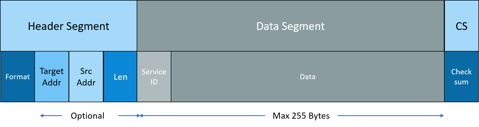
The header contains information about the packet. The data section typically has a service ID followed by a data section as specified by the higher-layer protocol. The total data section can go up to 255 bytes in length. Finally, there is a Checksum section — essentially an 8-bit sum of all bytes in the packet including the header but excluding the checksum byte itself.
The header format of the KWP2000 protocol contains information about the rest of the packet. The header can have up to 4 bytes in size, each of which are:
Format — Specifies information about the rest of the header. The MSB bits D7 and D6 (called A1 and A0) provide information about the target address:| D7 (A1) | D6 (A0) | Description |
|---|---|---|
| 0 | 0 | No address information is present |
| 0 | 1 | Exception mode of addressing |
| 1 | 0 | Physical address is being transmitted |
| 1 | 1 | Functional address is being transmitted |
The lower 5 bits specify the data section ranging between 1 and 63 with no length field present in the header. When it is 0, the header contains the length field which can go from 1 to 255.
Target address — The ECU being addressed, which could be a physical address or a functional address. When functional address is used, the ECUs respond one by one and organize themselves using simple collision-detection-based arbitration mechanism.The KWP2000 protocol can also be used on the CAN physical layer. While there are different higher-layer protocols over which KWP2000 can be run, most OEMs use ISO-15765 a.k.a. DoCAN protocol to run the KWP2000 on. As this transport protocol supports sending packets up to 4GB, it can easily accommodate the 255 + 5 bytes of the KWP2000.
In this section, let us explore the service frame format of the KWP2000 protocol and how to decode KWP2000 code values.
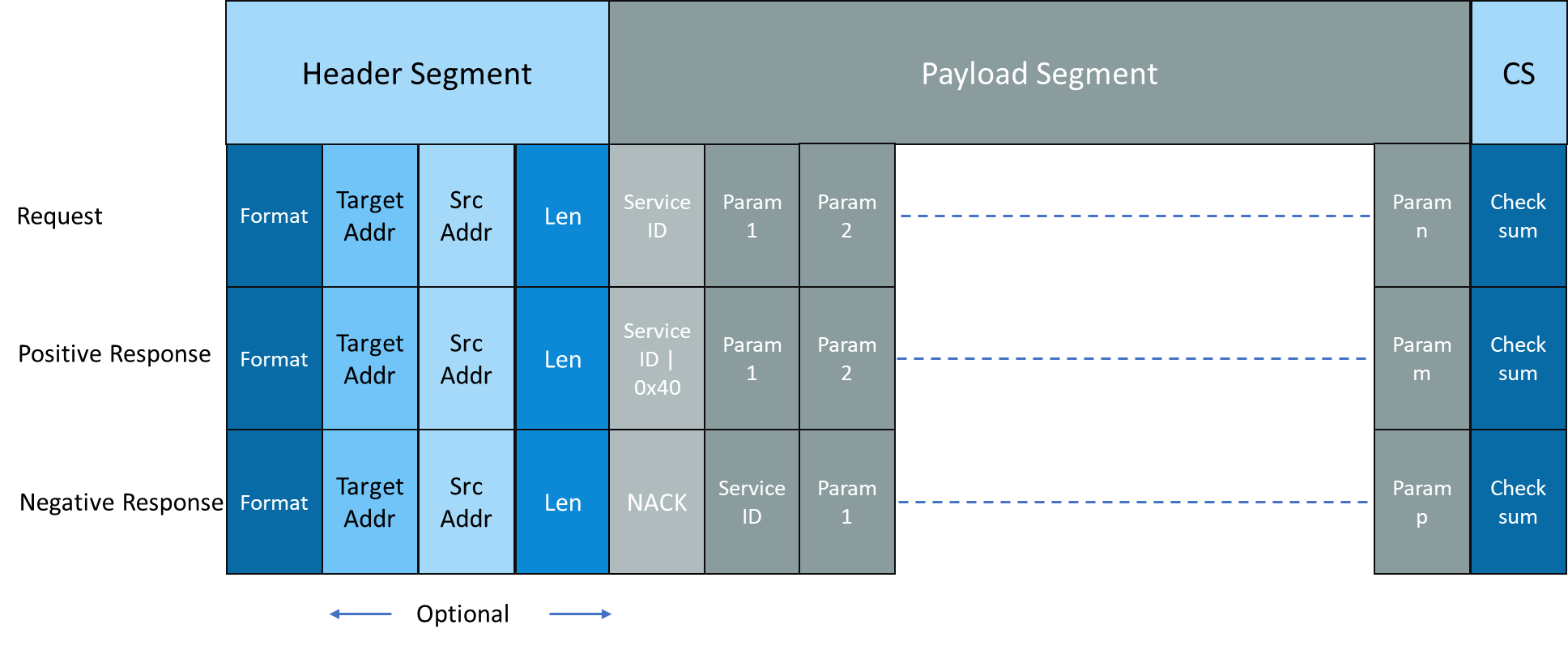
As seen earlier, the first part of the data section is always the KWP2000 code (service ID) indicating the service requested, followed by the parameters associated with that particular service. The KWP2000 code table is defined clearly by the specification.
For positive response, the first byte is the request KWP2000 code OR'ed with 0x40 followed by response parameters. For example, for the start diagnostic session request whose KWP2000 code is 0x10, the positive response code is 0x50. For negative response, the negative response code is the first byte followed by the requested service ID and error-specific response information.
The KWP2000 protocol groups multiple services under functional units, making it one of the structured vehicle diagnostics systems of its era. Vehicle diagnostics systems built on KWP2000 typically use these functional units to organize their diagnostic workflows:
| Functional Unit | Description |
|---|---|
| Diagnostic management | For general management of the diagnostic link |
| Data transmission | Perform data transmission between client and server including read/write data, memory, etc. |
| Stored data transmission | To perform transmission of data stored such as DTC (Diagnostic Trouble Codes) |
| Input/output control | Aids management of input/output ports of the server |
| Remote activation of routine | Used to perform routines on the server |
| Upload/download | Services to transfer large data between the server and client |
Modern vehicle diagnostics systems often migrate from KWP2000 to UDS, but the functional unit model has been carried forward. For cross-domain embedded engineering that includes KWP2000 and modern vehicle diagnostics systems, see our cross-domain embedded services.
Understanding where the KWP2000 protocol sits relative to the UDS diagnostic protocol is important for teams managing legacy and modern ECUs simultaneously. The UDS diagnostic protocol (ISO 14229) is the successor to KWP2000, inheriting many of its service concepts while adding structured session types, security access layers, and transport independence. KWP2000 protocol implementations on K-line are typically found in older vehicles and motorcycles, while the UDS diagnostic protocol is mandated in most post-2008 OBD-compliant vehicles. Teams supporting both protocols should design vehicle diagnostics systems that can switch between KWP2000 and UDS gracefully.
For service centers and testers looking for automotive diagnostics near me capabilities with KWP2000 support, the protocol is accessible via the standard OBD2 J1962 connector using K-line pins. Automotive diagnostics near me tools that support KWP2000 protocol can read and clear legacy DTCs, access vehicle data, and perform routine control functions. Embien's automotive diagnostics services and software-defined vehicle consulting help OEMs plan protocol migration paths for fleet-wide vehicle diagnostics systems.
The KWP2000 protocol has played a significant role in automotive diagnostics and vehicle diagnostics systems for many years. As automotive technology continues to advance, this protocol still remains a crucial tool for many legacy use cases. By demystifying the intricacies of the KWP2000 protocol — including its OSI mapping, K-line physical layer, initialization processes, KWP2000 code structure, header format, communication services, and functional units — one can easily work with legacy vehicle diagnostics systems. Its successors such as the UDS diagnostic protocol have taken its concepts further, but KWP2000 remains relevant wherever legacy ECUs are deployed.

Embien's product engineering services cover KWP2000 protocol integration, vehicle diagnostics systems development, and migration to modern UDS-based diagnostic solutions.
Embien's cybersecurity services help protect KWP2000 protocol implementations and vehicle diagnostics systems from unauthorized access and diagnostic port exploitation.
A serial protocol implementation for a PSTN dialler device, demonstrating Embien's expertise in automotive and industrial communication protocols akin to the KWP2000 protocol.