
Adaptive Cruise Control (ACC) represents one of the earliest and most widely deployed ADAS features in production vehicles today. Functional safety on adaptive cruise control is central to how OEMs and Tier-1 suppliers approach the design, integration, and certification of these systems. Unlike conventional cruise control, which simply holds a driver-set speed, ACC actively monitors the road ahead, detects vehicles in the same lane, and automatically adjusts the host vehicle speed to maintain a safe following distance.
What makes ACC engineering-challenging is that it sits precisely at the boundary between comfort and safety. A poorly designed ACC that brakes unexpectedly or accelerates into a closing gap is not just annoying — it is dangerous. This places meaningful ASIL requirements on the system and demands tight coordination between the ACC ECU and several other vehicle systems including the engine, brakes, and instrument cluster.
With the rapid progression toward higher SAE autonomy levels and the rise of software-defined vehicles, ACC is also the springboard for more advanced functions — Traffic Jam Assist, Highway Pilot, and ultimately hands-free highway driving. Understanding functional safety on adaptive cruise control is therefore foundational to understanding how the vehicle longitudinal control stack is built and certified.
This article covers the hardware and software architecture focussing on functional safety on adaptive cruise control — its safety requirements, design challenges, and future evolution of the ACC ECU.
Governing Standards: ISO 15622 defines the performance and test requirements for ACC systems. UNECE Regulation 131 governs Advanced Emergency Braking, which shares hardware infrastructure with ACC. ISO 26262 compliant automotive development applies for functional safety, typically targeting ASIL B at the system level. Achieving ASIL B certification requires systematic ISO 26262 compliant automotive development processes covering hazard analysis, safety goals, system design, implementation, and verification. Any ACC program targeting automotive series production must demonstrate full ISO 26262 compliant automotive development at both hardware and software levels.
ACC ECUs in production vehicles typically run on an Infineon AURIX TC3xx or Renesas RH850/U2A family microcontroller. These are chosen for their lockstep dual-core architecture (supporting ASIL B decomposition), integrated hardware security modules, and extensive automotive qualification pedigree. Clock speeds in the 200–300 MHz range are common. The availability of hardware floating-point units matters because the control algorithms involve significant real-time matrix computation. The functional safety on adaptive cruise control hardware layer must satisfy:
AUTOSAR or Bare-Metal?
ACC ECUs in production are almost universally built on AUTOSAR Classic, with the application layer decomposed into well-defined Software Components (SWCs) connected through the RTE. Adaptive AUTOSAR is emerging for next-generation centralised ADAS compute platforms, but Classic remains dominant for standalone ACC ECUs today. Functional safety on adaptive cruise control at the software layer is enforced through structured AUTOSAR BSW modules that provide deterministic scheduling, watchdog supervision, and fault management.
Relevant BSW Modules
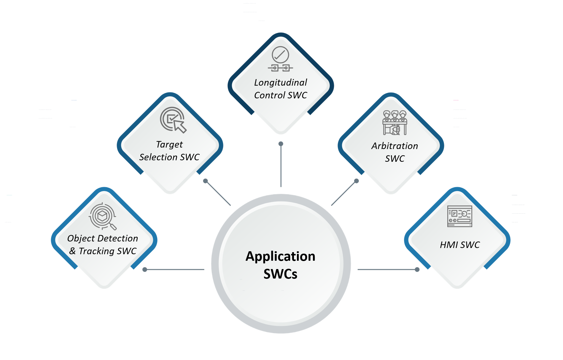
Object Detection & Tracking SWC: Receives the radar object list (range, range rate, azimuth for each detected object). Applies a Kalman filter to smooth object position and velocity estimates across measurement cycles. Maintains a track list of up to N objects, assigning confidence scores and predicting future positions between radar scan cycles (typically 50–100 ms).
Target Selection SWC: From the tracked object list, selects the Most Relevant Object (MRO) — the vehicle directly ahead in the host lane. Uses steering angle and yaw rate to project the host vehicle future path and identify which tracked object lies within it. Camera lane data provides additional lane assignment confidence.
Longitudinal Control SWC: Implements the core control law, typically a Model Predictive Control (MPC) or cascaded PID loop, that calculates the required longitudinal acceleration to achieve the target gap or set speed. Outputs a signed acceleration demand (positive for throttle, negative for brake). Applies jerk limiting (rate-of-change of acceleration) to ensure smooth, non-startling responses.
Arbitration SWC: Interfaces with the torque/brake request signals from other vehicle systems (driver pedal, ESC, etc.) and manages priority. The driver always overrides. ESC emergency braking always overrides. ACC operates in the space beneath these.
HMI SWC: Translates internal ACC state into signals consumed by the cluster or HUD — target lock symbol, set speed display, gap setting indicator, warning chime trigger.
The time gap (headway) maintained by ACC is expressed in seconds — a 1.5-second gap at 100 km/h corresponds to approximately 41 metres of following distance. The control law continuously computes the gap error and gap rate error and applies weighted corrections to the acceleration demand. Calibration of these weights is a significant validation activity requiring test track time.
ASPICE Compliance (Automotive SPICE) defines the process framework governing software development quality for automotive systems. For ACC ECUs, ASPICE Compliance is increasingly mandated by OEMs as a contractual requirement alongside ISO 26262. Implementing ASPICE Compliance ensures that requirement management, architecture design, integration, and verification activities are fully traceable and auditable throughout the program lifecycle.
ACC ECUs support UDS (ISO 14229) diagnostics via the vehicle CAN. Key DTC categories include radar blockage detection, camera unavailability, internal ECU faults, and communication timeouts from peer ECUs. In the event of a fault, the ECU transitions to a safe state (typically: ACC standby, driver alert via cluster) and logs the relevant DTC.
ASIL Rating: At the system level, functional safety on adaptive cruise control is typically rated ASIL B, reflecting the fact that the driver retains full override authority at all times, reducing controllability severity compared to steering or braking-only systems. Specific safety goals (e.g., "ACC shall not command braking exceeding X g without driver awareness") are derived during HARA. ISO 26262 compliant automotive development at ASIL B requires both hardware and software safety mechanisms to be formally documented, verified, and validated against those safety goals.
Ensuring functional safety compliance for embedded systems in ACC requires end-to-end traceability from safety goals through hardware requirements, software design, and verification evidence. Key safety mechanisms include:
ISO 21434 relevance: ACC ECUs are in-scope for automotive cybersecurity given their CAN-bus interfaces and potential for spoofed radar object injection. Robust functional safety compliance for embedded systems must address both safety and security threat vectors concurrently.
1. Object Selection in Complex Traffic: Multi-lane highways, merging vehicles, and curved roads all create scenarios where selecting the wrong Most Relevant Object causes nuisance braking or failure to brake. Robust path prediction using yaw rate integration and camera lane data is essential but hard to calibrate across all edge cases.
2. Radar and Camera Calibration Drift: Mounting angle errors as small as 0.5° in the radar can cause the MRO to be misidentified. Production end-of-line calibration and in-service monitoring (using stationary guardrail returns as reference) are both required.
3. Latency Budget Management: From radar return to brake actuation, the total system latency budget is typically under 200 ms. Each processing stage — radar DSP, object list transmission, ACC algorithm cycle, CAN transmission, ESC response — consumes a slice of this budget. Automotive functional testing automation tools are critical for systematically exercising these timing boundaries across all traffic scenarios without exhaustive manual test drives.
4. Jerk and Comfort Calibration: Technically correct braking that feels abrupt will cause drivers to disable ACC permanently. The comfort calibration — jerk limits, gap distance defaults, hysteresis bands — is as important as the control law itself. Automotive functional testing automation tools enable the repeatability and scenario coverage that manual testing cannot achieve at scale.
5. Stop-and-Go Extension: Extending ACC to full stop (0 km/h) requires integration with the electric parking brake or brake hold function, plus a pull-away logic that waits for driver intent confirmation before resuming following — a significant state machine complexity addition.
ACC is rapidly being absorbed into broader Highway Driving Assist (HDA) and Traffic Jam Assist (TJA) feature stacks, which combine longitudinal control (ACC) with lateral control (Lane Keeping Assist) into a unified domain controller. As part of the broader automotive digital transformation wave, OEMs are migrating ACC and ADAS workloads onto centralised ADAS SoC platforms (Qualcomm SA8775P, Renesas R-Car V4H) — treating functional safety on adaptive cruise control as a software partition rather than a dedicated ECU.
Radar technology is simultaneously moving from single-chip 77 GHz transceivers to 4D imaging radar, which adds elevation data to the traditional range-velocity-azimuth output, dramatically improving object classification and reducing false positives in complex scenarios.
Regulatory pressure is also increasing. Euro NCAP's 2025+ ratings now include ACC performance in real-world testing scenarios, creating a direct commercial incentive for OEMs to improve system robustness beyond minimum compliance.
Functional safety on adaptive cruise control is one of the most demanding engineering challenges in modern vehicle development. The ACC ECU design calls for careful consideration across hardware, software, and safety domains — underpinned by both ISO 26262 compliant automotive development and ASPICE Compliance processes. Embien has hands-on experience in developing and integrating ECU software for longitudinal control systems, AUTOSAR Classic-based application SWCs, and CAN/CAN FD communication stacks across multiple OEM programs. Our RAPIDSEA suite includes production-ready CAN FD and UDS protocol stacks that significantly reduce integration time on ACC and ADAS-adjacent programs. We have worked with Renesas RH850 and NXP S32K silicon families in safety-relevant ECU developments and can support ASIL B programs — covering functional safety compliance for embedded systems — from concept through validation.
To discuss your ACC or ADAS ECU development requirements, reach out to the Embien team.

Embien’s expertise across industries enables reliable functional safety implementation, resilient embedded architectures, and real-time control for adaptive cruise control systems.

Embien’s Cybersecurity Services strengthen adaptive cruise control systems with secure communication, threat mitigation, and resilient protection for safety-critical automotive functions.

A case study on oscillation measurement systems demonstrating precision signal acquisition, real-time monitoring, and reliable embedded system integration for industrial applications.