
Introduction
Working with AUTOSAR in practice means working with ARXML files and specialised toolchains, not writing C code from a blank file. The AUTOSAR development workflow is fundamentally tool-driven, where architecture descriptions in ARXML serve as the single source of truth from which code, configurations, and interface contracts are generated. Understanding this workflow is essential for anyone joining an AUTOSAR program.
This article walks through the standard development workflow that applies across vendor toolchains, from OEM system design through to ECU flash and validation.
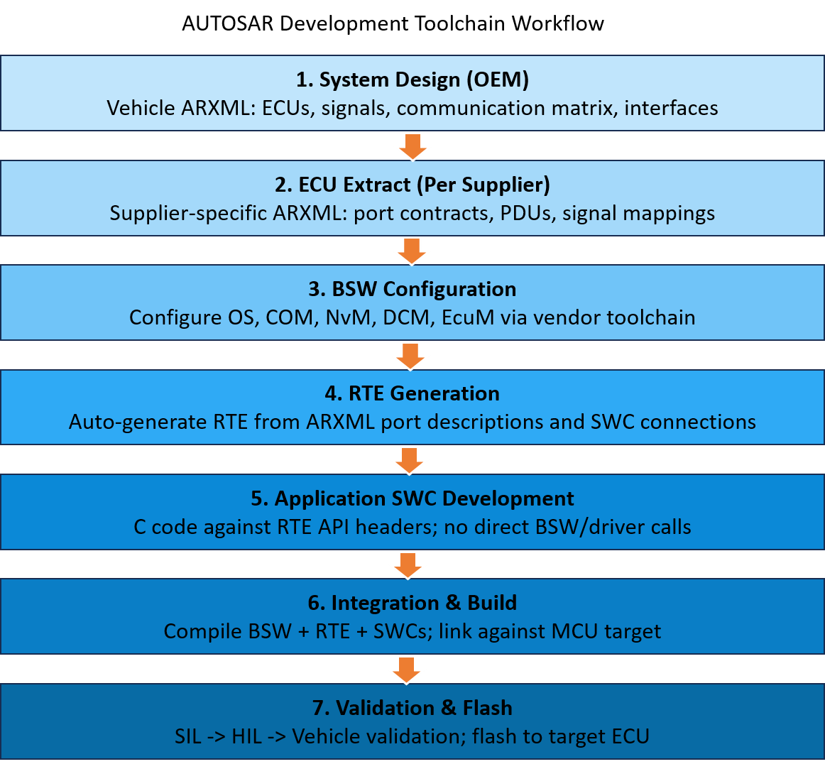
Step 1 - System Design (OEM Level)
The process begins at the OEM level. System architects define the full vehicle communication matrix in a system-level ARXML file: which ECUs exist, which signals they send and receive, at what cycle rates, and with what data types. This master ARXML is the contract that governs the entire supply chain. It specifies every signal, PDU, and interface boundary across all ECUs in the vehicle. Any change at this level cascades downstream to every supplier.
Step 2 - ECU Extract Generation
From the system ARXML, ECU-specific extracts are generated for each supplier. Each extract contains only the interface contracts relevant to that supplier’s ECU - the ports their SWCs must provide and require, the PDUs they transmit and receive, and the signal mappings for their CAN, LIN, or Ethernet communication. This extract is the starting point for all supplier-side development work.
Step 3 - BSW Configuration
With the ECU extract in hand, engineers configure the Basic Software modules for their specific ECU hardware using vendor configuration tools. This step involves setting up CAN channels and baud rates, defining PDU routing tables, configuring the OS task schedule and stack sizes, setting up NvM blocks for non-volatile storage, and configuring diagnostic services and DTC definitions.
The configuration is entirely ARXML-driven. Engineers work through graphical configurators that validate parameter combinations against AUTOSAR schema rules, catching integration errors before a single line of C code is compiled. The configurator then generates the BSW module source and configuration files.
Step 4 - RTE Generation
The Runtime Environment is auto-generated from the ARXML descriptions of all SWC port connections. The engineer does not write the RTE - the tool generates it, ensuring that port connections are type-correct and that scheduling constraints are consistent. The RTE generator produces the header files and glue code that wire application SWCs to BSW services and to each other, strictly through the declared port interfaces.
Step 5 - Application SWC Development
Engineers write C code for their application Software Components against the generated RTE API. The RTE header files define exactly which functions to call for reading inputs and writing outputs. An application developer never calls a CAN driver function or BSW module directly - they call RTE APIs that abstract the entire underlying stack. An SWC reading vehicle speed does not know whether that speed arrives from a CAN message, a local sensor, or another SWC’s output. It simply reads from its port. The RTE handles the rest.
Step 6 - Integration and Build
BSW generated code, RTE generated code, and application SWC source files are compiled and linked together for the target MCU. The build system pulls together all AUTOSAR-generated artefacts with the application code into a single flashable binary. Static analysis, MISRA checks, and unit testing are typically executed as part of this stage.
Step 7 - Validation and Flash
Validation proceeds through a structured sequence. Software-in-the-Loop (SIL) testing validates application logic in a simulated environment. Hardware-in-the-Loop (HIL) testing validates the integrated software on the actual ECU hardware against simulated vehicle signals. Finally, vehicle-level integration confirms end-to-end behaviour on the target platform. The final binary is flashed to the ECU for production deployment.
The Role of ARXML Throughout
ARXML is the backbone of the entire workflow. It is not merely a configuration file, it is the formal, machine-readable architecture description that drives every tool in the chain. System interfaces, SWC port definitions, BSW module parameters, communication matrices, and scheduling constraints are all captured in ARXML. When a signal name changes at the OEM level, that change propagates through ARXML extracts, BSW configuration, RTE generation, and into application code, maintaining traceability from system requirement to implementation.
The Learning Curve
This toolchain-driven workflow is the steepest part of the AUTOSAR learning curve for engineers coming from bare-metal backgrounds. The shift from writing C code directly against registers to configuring ARXML descriptions and generating code from them requires a fundamentally different mindset. The payoff, however, is a system where the architecture is formally described, tool-verified, and significantly more portable across programs and hardware generations. Our ECU Engineering Services, backed by expertise across industries, enable seamless AUTOSAR development from system design to reliable ECU integration and flashing.
What Comes Next
In the next article, we will examine how AUTOSAR supports ISO 26262 functional safety, from ASIL classification and decomposition to the architectural mechanisms that enable freedom from interference across mixed-criticality ECU software.