
No single sensor can see the world the way a safe autonomous or semi-autonomous vehicle needs to. Radar measures distance and velocity with precision in rain and fog but cannot reliably distinguish a pedestrian from a traffic cone. A camera provides rich object classification and lane detection but is blinded by glare and struggles with accurate depth estimation. LiDAR produces dense, accurate three-dimensional point clouds but is expensive, sensitive to adverse weather, and produces no velocity data directly.
Sensor fusion exists because the gaps in each sensor's capability are covered by the strengths of the others. A fused perception system that combines radar, camera, and LiDAR can detect, classify, and track objects with a level of reliability and confidence that no individual sensor can approach alone. The ECU that performs this fusion, the ADAS Sensor Fusion ECU or Perception ECU,is therefore one of the most computationally intensive, architecturally complex, and safety-critical units in the modern vehicle.
Understanding how this ECU is built,how sensors are integrated, how fusion algorithms operate, how safety requirements are managed, and how the software is structured, is foundational knowledge for any engineer working on ADAS, autonomous driving, or next-generation vehicle platforms.
The Sensor Fusion ECU's primary function is to receive raw or pre-processed data from multiple sensors, combine them into a single coherent world model, and output a unified, confidence-weighted object list that downstream ADAS consumers, ACC, Autonomous Emergency Braking (AEB), Lane Keeping Assist (LKA), and Path Planning, can rely upon.
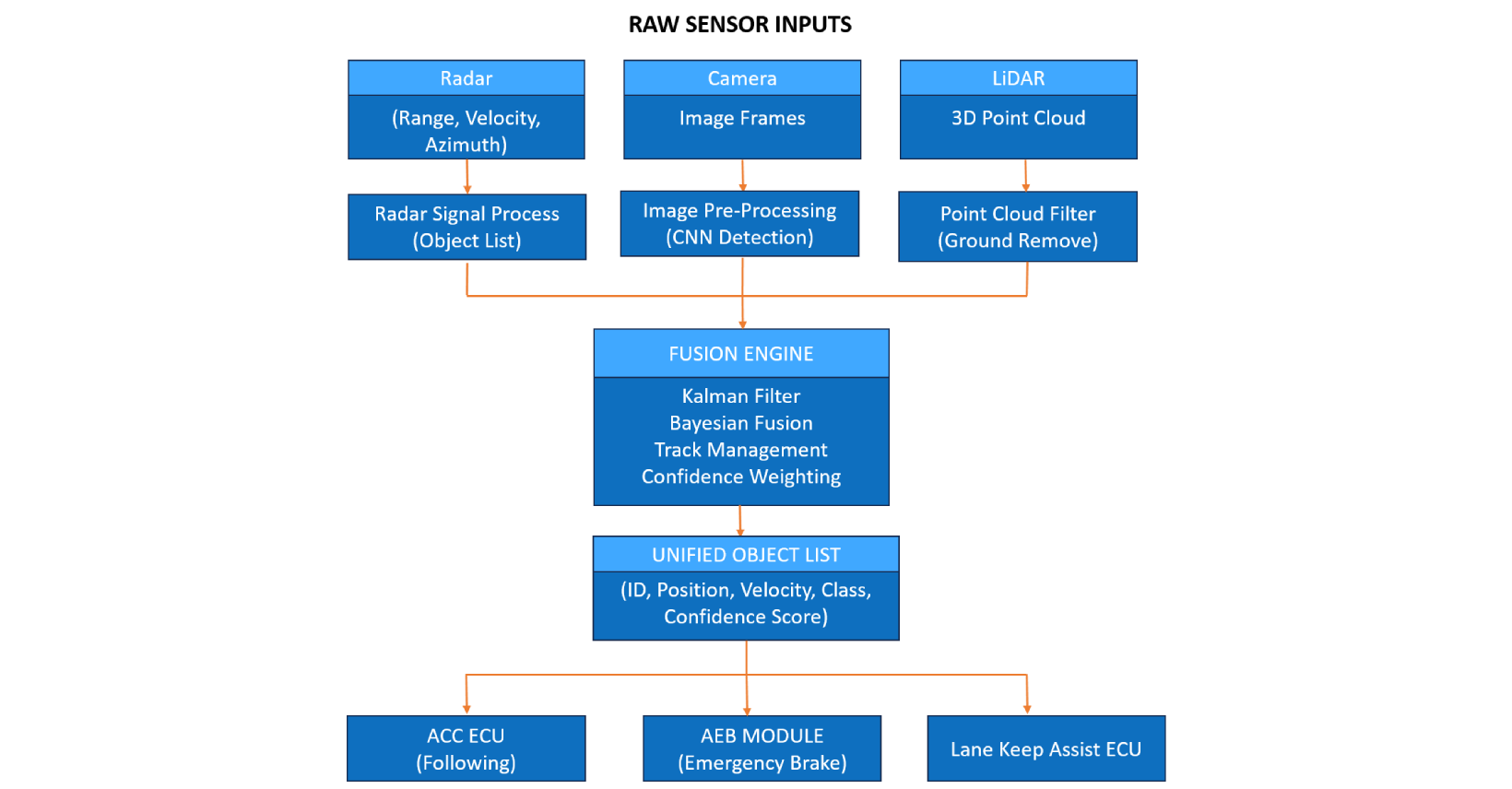
Key Inputs:
Key Outputs:
| Mode | Description |
|---|---|
| Full Fusion | All sensors available and contributing |
| Degraded Fusion | One sensor unavailable - reduced confidence, ADAS consumers notified |
| Camera Only | Radar/LiDAR fault - limited object list, downstream features restricted |
| Standby | Vehicle stationary, sensor heating/initialisation |
| Diagnostic | Full UDS diagnostics, sensor calibration routines |
Governing Standards: ISO 26262 applies at ASIL B for most fusion outputs feeding ACC and LKA. AEB-feeding outputs may require ASIL C or ASIL D depending on system architecture. ISO 21448 (SOTIF - Safety Of The Intended Functionality) applies specifically to the performance limitations and foreseeable misuse scenarios of the perception system, a standard unique to ADAS that addresses failures caused not by hardware faults but by the algorithm encountering situations outside its design domain.
Processor
The computational demands of real-time sensor fusion, processing radar object lists at 20 Hz, camera frames at 30 fps, and LiDAR point clouds at 10–20 Hz simultaneously, place this ECU firmly in the domain of high-performance System-on-Chip (SoC) processors, not conventional automotive MCUs.
Typical silicon choices include the Renesas R-Car V4H, Qualcomm SA8775P, and NXP S32G series. These SoCs combine multi-core ARM Cortex-A application processors (for fusion algorithms and object tracking) with dedicated hardware accelerators, the Renesas DRP-AI, Qualcomm Hexagon DSP, or NXP eIQ NPU, for the convolutional neural network inference that underpins camera-based object detection.
For safety-critical partitions, particularly the output arbitration and object list validation logic, a separate lockstep MCU (such as an RH850 or AURIX core) often runs alongside the main SoC, providing ASIL-capable monitoring of the SoC's outputs. This heterogeneous architecture, high-performance SoC for computation, lockstep MCU for safety supervision, is the dominant pattern in production ADAS ECUs today.
Memory
LPDDR4/5 RAM: 4–16 GB for the main SoC, holding live sensor data buffers, neural network model weights, object track lists, and HD map tiles
eMMC / NVMe Flash: 32–256 GB for OS, application software, neural network models, and OTA update partitions
SRAM (safety MCU): 1–2 MB for safety supervision logic and monitored output buffers
Data Flash: DTC storage, calibration parameters, operational event logs
Communication Interfaces
100BASE-T1 / 1000BASE-T1 Automotive Ethernet: Primary interface for high-bandwidth sensor data, camera streams and LiDAR point clouds cannot be carried on CAN
CAN FD: Vehicle dynamics inputs from ESC, EPS, and other chassis ECUs; output of object list summary signals to legacy ADAS consumers
GMSL / FPD-Link (SERDES): High-speed serialiser/deserialiser links for camera sensor interfaces, a single GMSL2 link carries up to 6 Gbps of raw image data
PCIe: Internal interface to LiDAR processing module in some integrated designs
Power Supply
The fusion SoC is power-hungry, typical total ECU power consumption is 15–30W. A sophisticated power management architecture with multiple DC-DC stages, thermal monitoring, and dynamic frequency scaling is required. The safety MCU maintains its own independent power supply domain with hardware-enforced separation from the main SoC supply.
Safety Hardware
AUTOSAR Classic vs Adaptive - The Fusion ECU Case
This is the ECU where AUTOSAR Adaptive makes its strongest case. The sensor fusion application is not a fixed-function control loop running at a deterministic rate, it is a complex, layered software stack involving OS-level process management, dynamic service discovery, neural network runtime environments, and over-the-air model updates. Classic AUTOSAR's static configuration model is a poor fit.
In practice, most production ADAS Fusion ECUs run a hybrid architecture:
SOME/IP service discovery over Automotive Ethernet connects the fusion outputs to consuming ADAS applications across the vehicle network.
Key Software Components
Sensor Driver and Pre-Processing Layer: Each sensor type requires dedicated driver software. Camera drivers handle MIPI CSI-2 or GMSL frame capture and feed raw frames to the image pre-processing pipeline (demosaicing, lens distortion correction, colour normalisation). Radar drivers receive pre-processed object lists via Ethernet or CAN from the radar front-end processor. LiDAR drivers handle point cloud ingestion and ground plane removal.
Object Detection SWC (Camera): A Convolutional Neural Network, typically a variant of YOLO, SSD, or a proprietary architecture, runs on the hardware AI accelerator and produces bounding boxes with class labels and confidence scores for every detected object in the camera frame. This runs at 20–30 fps. The network weights are loaded from flash at startup and may be updated via OTA.
Radar Object Tracking SWC: Maintains a Kalman filter track for each radar-detected object across scan cycles. The Kalman filter predicts each object's future position based on its current velocity, then corrects the prediction using the new radar measurement. This produces smooth, low-latency position and velocity estimates for each tracked object even between radar scan cycles.
Fusion Engine SWC: The core of the ECU. Associates radar tracks with camera detections using a Hungarian algorithm or similar assignment method, matching objects across sensor modalities based on spatial proximity and geometric consistency. Applies Bayesian confidence weighting, when radar and camera agree on an object's position and class, confidence is high; when they disagree, confidence is reduced and the disagreement is flagged for safety supervision. Maintains a unified object track list with merged attributes from all contributing sensors.
Three Fusion Architecture Approaches:
| Approach | Description | Trade-off |
|---|---|---|
| Early Fusion | Raw sensor data merged before detection | Maximum information but highest compute demand |
| Late Fusion | Each sensor detects independently, object lists merged | Lower compute, some information loss |
| Mid-level Fusion | Feature maps merged before classification | Balance of information richness and compute cost |
Most production systems use late fusion or mid-level fusion due to compute and latency constraints, with a trend toward mid-level fusion as SoC capability increases.
Safety Supervision SWC (on lockstep MCU): Monitors the fusion output for plausibility, checks that object positions are physically reasonable, that object velocities do not exceed physical limits, that confidence scores are consistent with sensor availability. Any output failing plausibility is flagged, and downstream ADAS consumers are notified via a validity flag on the object list. In the event of a detected SoC fault, the safety MCU transmits a degraded-mode object list derived from whichever sensors remain available and valid.
Diagnostic Layer: Full UDS support for sensor calibration routines (camera extrinsic calibration, radar boresight calibration), DTC readout, and live data streaming for development and service use. SOTIF-related monitoring, tracking how often the system encounters low-confidence scenarios, feeds into field data collection for ongoing model improvement.
ASIL Rating:ASIL B at the system output level for most object list consumers, with ASIL D decomposition applied to AEB-critical outputs. The heterogeneous SoC + lockstep MCU architecture enables ASIL decomposition, the SoC runs QM/ASIL B application software while the lockstep MCU provides the ASIL D safety supervision channel.
ISO 21448 (SOTIF):Unique to ADAS. SOTIF addresses the scenario where the system works correctly as designed but produces an unsafe outcome due to performance limitations, for example, a pedestrian in an unusual pose that the detection neural network has not encountered in training. SOTIF compliance requires systematic identification of triggering conditions, evaluation of sensor coverage gaps, and ongoing field monitoring.
Key Safety Mechanisms:
The trajectory is clear: sensor fusion is moving from distributed ECUs toward centralised high-performance compute (HPC) platforms, single powerful computing units (NVIDIA DRIVE AGX, Qualcomm Ride, Renesas R-Car series) handling perception, fusion, planning, and control for the entire vehicle. On these platforms, the sensor fusion function becomes a software stack rather than a dedicated ECU.
4D imaging radar, which adds elevation to the traditional range-velocity-azimuth output, is reducing the gap between radar and LiDAR capability, enabling robust 3D object detection without the cost and complexity of a LiDAR sensor. This may shift many Level 2+ applications to radar-camera fusion, reserving LiDAR for Level 3 and above.
Embien has hands-on experience with ADAS perception system development, camera and radar sensor integration, and high-performance embedded computing platforms including NVIDIA Jetson, Renesas R-Car, and Qualcomm-based SoCs. Our embedded vision expertise spans the full pipeline from sensor driver development through inference engine optimisation. We have delivered ASIL-B compliant embedded software for chassis-adjacent safety applications and are experienced with AUTOSAR Adaptive middleware on Linux-based automotive platforms.
To discuss your ADAS sensor fusion or perception system development requirements, reach out to the Embien team.
Embien's embedded computing platforms provide the processing foundation for automotive and industrial applications, from low-power MCU-based designs to high-performance SoC solutions.
Embien offers comprehensive electronics product development services, covering schematic design, PCB layout, prototyping, and production-ready embedded system development.
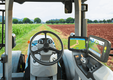
A case study on instrument cluster development for an electric tractor — showcasing Embien's embedded systems expertise in CAN integration, motor control display, and automotive-grade MCU programming.