
Introduction
Part 1 of this series covered the structural fundamentals of J1939 diagnostics, PGN and SPN architecture, address claiming, and the DM1/DM2 message framework. This piece picks up exactly where that left off: the practical work of actually reading a DM1 or DM2 message off the bus and turning its raw bytes into an actionable fault diagnosis. Getting comfortable with SAE J1939 protocol software at this byte-decoding level is what separates a technician or engineer who can look up a fault code in a table from one who can independently verify what a diagnostic tool is telling them and troubleshoot when the tool itself is giving an ambiguous answer.
In short: DM1 broadcasts a vehicle's currently active faults every second while DM2 holds the history of faults that have since cleared, both messages package each fault as an SPN-FMI-occurrence-count triplet inside a fixed byte layout that transport-protocol segmentation splits across multiple CAN frames when there are enough active faults to exceed a single frame's payload, and being able to decode that byte layout directly, not just read a decoded value off a scan tool's screen, is what real J1939 diagnostic troubleshooting requires when the easy path doesn't give a clear answer.
Quick Recap of J1939 PGN/SPN Structure From Part 1
A brief recap for readers arriving here directly: J1939 organizes vehicle data into Parameter Group Numbers (PGNs), each PGN a defined message type with a specific byte layout, and within each PGN, individual data values are identified by Suspect Parameter Numbers (SPNs), the atomic unit of J1939 data. A diagnostic fault is reported as an SPN paired with a Failure Mode Identifier (FMI) that describes how the parameter is faulting, SPN 110 FMI 3, for example, identifies an engine coolant temperature signal reading voltage above normal. DM1 and DM2 are the two PGNs specifically dedicated to carrying these SPN-FMI fault pairs, DM1 for currently active faults and DM2 for faults that were active in the past but have since cleared. Readers wanting the full protocol-layer detail behind this summary should see Part 1 of this series.
DM1 (Active) vs DM2 (Previously Active) Diagnostic Messages
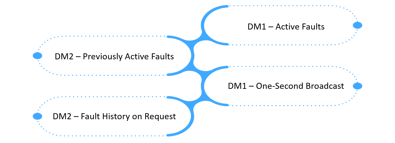
DM1, PGN 65226 (0xFECA), is broadcast continuously by each ECU at one-second intervals whenever at least one active fault is present, and an ECU with no active faults still transmits DM1 with all lamps off and no fault data, giving a positive, continuously-refreshed "all clear" signal rather than simple silence, which matters because silence alone can't distinguish "no faults" from "the ECU stopped communicating." DM2, PGN 65227 (0xFECB), by contrast, holds the history of faults that were active at some point but have since cleared, and is transmitted on request via the Request PGN rather than broadcast continuously, making it the message a technician specifically queries to investigate an intermittent fault that isn't currently active but clearly happened at some point in the vehicle's recent operating history.
Reading and Decoding Fault Code Fields in Practice: The Byte Layout
Both DM1 and DM2 share the same data structure after their first two bytes. Byte 1 carries the lamp status word, packing the Malfunction Indicator Lamp, Red Stop Lamp, Amber Warning Lamp, and Protect Lamp states, each as a two-bit field, into a single byte, with byte 2 carrying flash-rate information for those same lamps. From byte 3 onward, the message repeats a four-byte fault entry for each active or stored fault: two bytes encoding the SPN's lower bits, a byte combining the SPN's upper bits with the FMI, and a final byte combining an SPN-conversion-method flag with an occurrence count showing how many times that specific fault has been detected since it first became active. Decoding a raw DM1 frame by hand means extracting the SPN's bits from across those two-and-a-partial-byte fields correctly, a detail that trips up more homegrown decoding implementations than any other part of the message, and cross-referencing the resulting SPN and FMI numeric values against the J1939-71 and J1939-73 standard's defined parameter and failure-mode tables to arrive at a human-readable fault description.
Common Fault Patterns in Heavy-Vehicle Diagnostics
Certain SPN-FMI combinations recur often enough in heavy-vehicle fleets that recognizing the pattern speeds diagnosis considerably. An SPN paired with FMI 3 (voltage above normal, or shorted to a high source) or FMI 4 (voltage below normal, or shorted to a low source) points toward a wiring or connector fault, an open circuit, a short to power or ground, rather than the sensor or actuator itself having failed internally, and is usually the first thing worth checking given how much more common wiring faults are in the field than genuine component failure. An SPN paired with FMI 2 (data erratic, intermittent, or incorrect) frequently indicates a marginal connector or a communication issue upstream of the actual sensor rather than the sensor reading itself being wrong. And a cluster of unrelated SPNs all reporting communication-timeout FMIs simultaneously is a strong signal of a network-level problem, a failing terminating resistor, a damaged backbone segment, rather than several unrelated component failures happening to occur at once, a distinction that changes where a technician should actually start looking.
Tools and Techniques for J1939 Diagnostic Troubleshooting
Practical J1939 diagnostic troubleshooting typically layers three levels of tooling. A commercial heavy-vehicle scan tool handles the common case, decoding DM1/DM2 automatically and presenting a human-readable fault list without requiring manual byte decoding. A CAN bus analyzer capturing raw frames becomes necessary when a scan tool's decoded output looks wrong or incomplete, letting a technician verify the raw DM1 or DM2 bytes directly against the SPN-FMI decoding logic described above rather than trusting a black-box tool's interpretation. And for engineering teams developing or validating an ECU's own diagnostic reporting, a J1939 protocol stack and simulation environment capable of generating and injecting specific SPN-FMI fault conditions onto a bench network is what makes systematic diagnostic software validation possible before a vehicle ever reaches the field, rather than discovering decoding bugs only after fleet deployment.
SAE J1939 Protocol Software: Where the DM1/DM2 Decoding Logic Actually Lives
The DM1/DM2 decoding work described above isn't something every ECU or diagnostic tool implements from scratch correctly, and a substantial share of field diagnostic ambiguity traces back to subtly incorrect byte-decoding logic in SAE J1939 protocol software rather than to the underlying vehicle fault itself. Embien's RAPIDSEA suite includes a production J1939 stack covering the full DM message set from DM1 through DM19, correctly implementing the transport-protocol segmentation that spans multiple faults across several CAN frames, deployed across telematics control units, gateway ECUs, and diagnostic tooling for commercial vehicle customers, precisely the kind of verified decoding logic that removes byte-layout ambiguity as a source of field diagnostic confusion.
On Board Diagnostics Protocol: How J1939 Fits Alongside OBD-II and UDS
J1939 is one of several diagnostic protocol families a heavy-vehicle or off-highway engineer encounters, and understanding how it relates to the broader on board diagnostics protocol landscape helps place DM1/DM2 in context. Where OBD-II standardizes light-duty vehicle emissions diagnostics under a comparatively rigid, regulator-defined structure, and UDS (Unified Diagnostic Services) provides a general-purpose, session-based diagnostic services framework used heavily in automotive ECU development, J1939's DM message architecture is purpose-built for the broadcast, multi-ECU network topology of heavy trucks, buses, and off-highway equipment, prioritizing continuous fault visibility across the network over the request-response diagnostic session model UDS uses.
Automotive Diagnostics & Protocols: How This Fits a Broader Diagnostic Strategy
DM1/DM2 fault-code interpretation is one piece of a broader automotive diagnostics & protocols strategy that a heavy-vehicle OEM or fleet operator needs across a vehicle's development and field-service life: diagnostic coverage planned during ECU software design so the right SPN-FMI combinations get reported in the first place, robust protocol-stack implementation that decodes and transmits DM messages correctly under real bus conditions, and field diagnostic tooling and technician training that can act on that data effectively once a vehicle is in service. Treating DM1/DM2 interpretation as an isolated skill rather than one link in that end-to-end chain is where a lot of otherwise well-designed diagnostic systems fail to deliver their full value in practice.
J1939 DM1 and DM2 Fault Code Diagnostics Explained: A Worked Summary
In short: DM1 gives continuous visibility into what's wrong with a vehicle right now, DM2 gives the history of what has gone wrong recently, both encode faults as SPN-FMI pairs inside a shared four-byte-per-fault layout, and how to interpret J1939 diagnostic trouble codes correctly, whether reading a scan tool's decoded output or decoding raw bus frames directly, comes down to knowing that shared byte structure well enough to catch the cases, ambiguous FMI codes, transport-protocol segmentation, malformed frames, where a decoding tool's output can't simply be trusted at face value.
Embien's Capabilities
Embien brings production J1939 protocol stack development experience spanning the full DM message set, transport protocol segmentation, and multi-platform deployment across Renesas RH850, NXP S32K, and STM32, alongside broader automotive diagnostic protocol expertise across OBD-II and UDS. Our engineering process validates diagnostic byte-decoding logic against real fault-injection testing rather than assuming standard-compliant behavior from an unverified implementation.
To discuss SAE J1939 protocol software development or heavy-vehicle diagnostic protocol integration, reach out to Embien's engineering team.