
In the passenger vehicle world, OBD-II is the universal diagnostic language. Plug any generic scanner into the 16-pin OBD-II port, and you can read fault codes, live sensor data, and emissions-related parameters from virtually any car built after 1996. The protocol is standardised, the connector is standardised, and the data is largely accessible without proprietary tools.
Heavy commercial vehicles, trucks, buses, construction equipment, agricultural machinery, operate in a different world. Their electronic architectures carry far more ECUs, far more sensors, and far more complex powertrain and chassis systems than passenger cars. Their diagnostic and control communication needs are correspondingly richer. And they predate the OBD-II standardisation effort, the heavy vehicle industry had already developed its own networking standard by the time OBD-II arrived.
That standard is SAE J1939. Published by the Society of Automotive Engineers and based on the CAN bus physical layer, J1939 is the dominant communication and diagnostic standard for heavy-duty vehicles across North America, Europe, and increasingly globally. Understanding J1939 is essential for anyone developing ECUs, diagnostic tools, telematics systems, or fleet management solutions for commercial vehicles, agricultural equipment, marine engines, or off-highway machinery.
This article covers the protocol fundamentals, the message structure, addressing scheme, Parameter Group Numbers, Suspect Parameter Numbers, and the diagnostic message architecture that makes J1939 the lingua franca of heavy vehicle electronics.
OBD-II was designed for emissions monitoring in passenger cars. Its diagnostic services (Mode 01 through Mode 09, and Mode 0A for permanent fault codes) provide standardised access to a defined set of emissions-relevant parameters. The protocol is adequate for its intended purpose.
Commercial vehicles have needs that OBD-II cannot address. A Class 8 truck might have an engine ECU, a transmission controller, an ABS system, a retarder controller, an exhaust aftertreatment system, a body controller, a PTO controller, a trailer interface, and a tachograph, each requiring both control communication and diagnostic access. These systems must communicate with each other continuously, not just respond to a diagnostic tool on request.
J1939 provides: a peer-to-peer and broadcast communication architecture (not just tool-to-ECU); a standardised, extensible parameter database covering thousands of vehicle parameters across all heavy vehicle systems; multi-packet transport (for messages longer than 8 bytes); address claiming (allowing ECUs to negotiate addresses dynamically); and a diagnostic message architecture (DM messages) that is far richer than OBD-II Mode 03/07.
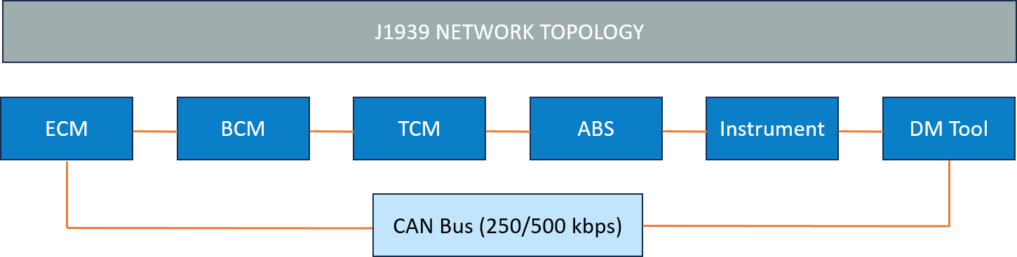
J1939 uses the CAN bus physical layer as defined by ISO 11898-2, the same physical layer used in passenger car CAN networks. The standard baud rate is 250 kbps (though 500 kbps and 1 Mbps are increasingly used for high-bandwidth segments). The connector is the 9-pin Deutsch connector (SAE J1939-13), the large round grey connector visible under the dash of North American trucks and on European heavy vehicles' diagnostic access points.
J1939 uses the 29-bit extended CAN identifier, not the 11-bit standard identifier used in many passenger car CAN implementations. This extended identifier encodes the priority, protocol data unit format, and source/destination addressing information directly in the CAN arbitration field, a key architectural decision that enables the J1939 protocol to function without a separate message header byte.
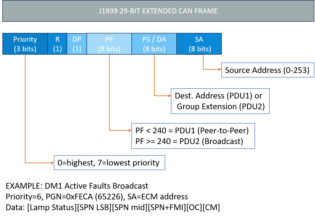
The 29-bit J1939 identifier carries six distinct fields:
Priority (3 bits): Values 0 (highest) through 7 (lowest). Control messages typically use priority 3. Diagnostic messages use priority 6. This ensures control-critical messages, engine torque commands, ABS brake request, always win bus arbitration over diagnostic traffic.
Reserved (R) and Data Page (DP) bits (2 bits): Provide additional PGN namespace capacity. DP=0 covers the standard J1939 PGN space. DP=1 extends the space for proprietary and future standard PGNs.
PDU Format (PF, 8 bits): The most structurally important field. When PF < 240 (0xF0), the message is PDU1 format, a peer-to-peer message addressed to a specific destination address. When PF >= 240, the message is PDU2 format, a broadcast message with no specific destination, where the PS field carries the Group Extension (part of the PGN).
PDU Specific (PS, 8 bits): In PDU1 messages: the Destination Address (DA) of the target ECU. In PDU2 messages: the Group Extension, which forms part of the Parameter Group Number.
Source Address (SA, 8 bits): The address of the ECU transmitting this message. Addresses 0–253 are available for ECUs. Address 254 is the null address. Address 255 is the global address (broadcast to all nodes).
A Parameter Group Number (PGN) identifies a specific set of related parameters, a 'message type' in J1939 terminology. Each PGN has a defined data structure: which bytes carry which parameters, the scaling factors, the offset, the data range, and the transmit rate.
PGNs cover an enormous range of vehicle functions, all defined in the SAE J1939-71 (Vehicle Application Layer) standard. Some widely used examples:
| PGN | Name | Content | Transmit Rate |
|---|---|---|---|
| 0xF004 (61444) | Electronic Engine Controller 1 (EEC1) | Engine speed, torque, demand | 10 ms |
| 0xF003 (61443) | Electronic Engine Controller 2 (EEC2) | Accelerator pedal, throttle | 50 ms |
| 0xFEF1 (65265) | Cruise Control/Vehicle Speed | Vehicle speed, cruise status | 100 ms |
| 0xFECA (65226) | DM1 - Active Diagnostic Trouble Codes | Lamp status + active fault list | 1 s / on change |
| 0xFECB (65227) | DM2 - Previously Active DTCs | Stored (inactive) fault history | On request |
| 0xFEDA (65242) | Software Identification | ECU software version strings | On request |
| 0xFED8 (65240) | Component Identification | ECU serial number, part number | On request |
The J1939-71 standard defines hundreds of PGNs. Proprietary extensions, using PGN ranges reserved for manufacturer-specific use, allow OEMs and Tier-1 suppliers to add parameters not covered by the standard without conflicting with standard PGNs.
Within each PGN, individual parameters are identified by Suspect Parameter Numbers (SPNs). An SPN identifies a specific physical or logical parameter, engine coolant temperature, vehicle speed, fuel level, brake applied status, with a defined position within the PGN data bytes, a scaling factor, and an offset.
SPNs are the atomic unit of J1939 data. When a diagnostic tool reads a fault code in J1939, the fault is reported as an SPN-FMI pair:
SPN (Suspect Parameter Number): Identifies which parameter is faulting — for example, SPN 110 is Engine Coolant Temperature.
FMI (Failure Mode Identifier): Identifies how the parameter is faulting, FMI 3 means 'Voltage above normal, or shorted to high source.' FMI 4 means 'Voltage below normal, or shorted to low source.' FMI 5 means 'Current below normal.' There are 32 defined FMI values covering the most common failure modes for sensors, actuators, and internal system faults.
The SPN-FMI combination provides significantly more diagnostic information than a simple fault code. A technician seeing SPN 110 FMI 3 (coolant temperature voltage above normal) knows immediately to check for an open-circuit sensor or a wiring fault to the sensor supply, before even looking at the vehicle.
Unlike OBD-II or a fixed CAN DBC, J1939 ECUs negotiate their addresses dynamically through the Address Claiming procedure defined in J1939-81.
When an ECU powers up on a J1939 network, it broadcasts its preferred address in a Claim Address message, a PGN 0xEE00 (60416) message containing the ECU's 8-byte NAME field, which encodes its manufacturer code, function, instance number, and industry group. If no other ECU on the network objects within 250 ms, the ECU assumes that address and begins normal operation.
If two ECUs claim the same address simultaneously, possible when hot-swapping modules or in complex multi-ECU configurations, the NAME field comparison determines which ECU wins. The ECU with the lower NAME value (numerically) retains the address; the other must re-claim with a different address or declare itself unable to claim (going off-network).
For engineers developing J1939 ECUs, implementing address claiming correctly, including the race condition handling, the re-claim logic, and the off-network state, is one of the first and most important protocol compliance requirements.
The J1939 diagnostic message set (DM messages, defined in J1939-73) is the most directly useful part of the protocol for service technicians and fleet managers. The two most important are:
DM1 - Active Diagnostic Trouble Codes: Broadcast continuously by each ECU at 1-second intervals whenever at least one active fault is present. The data contains the lamp status (Malfunction Indicator Lamp, Red Stop Lamp, Amber Warning Lamp, Protect Lamp, each mapped to J1939 severity conventions) followed by up to 88 active SPN-FMI pairs (using the multi-packet transport protocol for more than one fault). When no faults are active, the ECU transmits a DM1 with all lamps off and no fault data, providing a positive 'all clear' indication.
DM2 - Previously Active (Stored) Diagnostic Trouble Codes: Contains the history of faults that were active in the past but are no longer active. Transmitted on request (using the Request PGN 0xEA00). Service technicians use DM2 to investigate intermittent faults that cleared themselves.
Additional DM messages cover: DM3 (clear stored faults), DM4 (freeze frame data at time of fault), DM5 (ECU readiness status for emissions compliance), DM11 (clear active faults), DM14/DM15/DM16 (memory read/write, for ECU reprogramming), and DM19 (calibration verification number, used to verify ECU software integrity after programming).
The CAN frame carries a maximum of 8 data bytes. Many J1939 PGNs, particularly diagnostic messages with multiple fault entries, and software identification strings, need to carry more data than this. J1939-21 defines the Transport Protocol (TP) for multi-packet messages:
BAM (Broadcast Announce Message): Used for broadcast multi-packet messages (no specific destination). The sender first transmits a BAM announcing the number of packets and total bytes, then sends the data packets sequentially. All nodes on the network receive the data but only the application-layer listener processes it.
CMDT (Connection Mode Data Transfer): Used for peer-to-peer multi-packet messages. A full handshake protocol, connection request, clear-to-send, data transfer, end-of-message acknowledgement, ensures reliable delivery to the specific destination address. Embien's Automotive Electronics expertise enables reliable commercial vehicle ECUs, gateways, diagnostics, and in-vehicle communication systems.
| Aspect | J1939 | OBD-II | UDS (ISO 14229) |
|---|---|---|---|
| Target vehicles | Heavy commercial, off-highway | Passenger cars | Passenger cars, commercial |
| Identifier | 29-bit CAN extended | 11-bit CAN standard | 11-bit or 29-bit |
| Architecture | Peer-to-peer + broadcast | Tool-to-ECU only | Tool-to-ECU only |
| Parameter model | PGN / SPN | OBD PIDs (Mode 01-0A) | DID (Data Identifier) |
| Fault model | SPN + FMI | DTC (P/C/B/U codes) | DTC with status byte |
| Multi-packet | BAM / CMDT (J1939-21) | Not standard | ISO 15765-2 (CAN TP) |
| Programming | DM14/DM15/DM16 | Not defined | 0x34–0x37 services |
Embien's RAPIDSEA suite includes a production-ready J1939 stack covering the full protocol stack, address claiming, PGN transmit/receive, transport protocol (BAM and CMDT), and the complete DM message set from DM1 through DM19. The stack is available for Renesas RH850, NXP S32K, and STM32 platforms and has been deployed in telematics control units, gateway ECUs, and diagnostic tools for commercial vehicle customers.
Part 2 of this series will cover J1939 in the telematics context, how fleet management systems consume J1939 data from the vehicle network, the role of the telematics gateway in bridging J1939 to IP networks, and the security considerations for J1939 over telematics links.
To discuss J1939 stack integration or commercial vehicle ECU development requirements, reach out to the Embien team.

Embien delivers J1939-based embedded solutions across commercial vehicles, off-highway equipment, agriculture, marine, and industrial mobility applications.

Embien's Embedded Software Development Services accelerate production-ready J1939 stacks, gateway software, diagnostics, and ECU firmware development.

A case study on enabling remote ECU diagnostics and secure FOTA updates through an Android-based UDS client using RAPIDSEA, JNI integration, and Qualcomm-Renesas architecture.