
An ECU's manufacturability and testability are determined almost entirely during design, by the time layout is finalized and the design is released to a contract manufacturer, the major decisions that determine yield, test coverage, and production cost are already locked in. Design for manufacturing DFM, paired with design for test (DFT) decisions made alongside it, is what makes the difference between a board that comes off the line at high first-pass yield with straightforward, fast production test, and one that fights its own manufacturing and test process for the life of the program. Automotive electronics manufacturing carries higher stakes than most consumer design, volumes are large, quality expectations are strict, and a manufacturability problem discovered after layout is finalized is expensive in exactly the way this article is about avoiding.
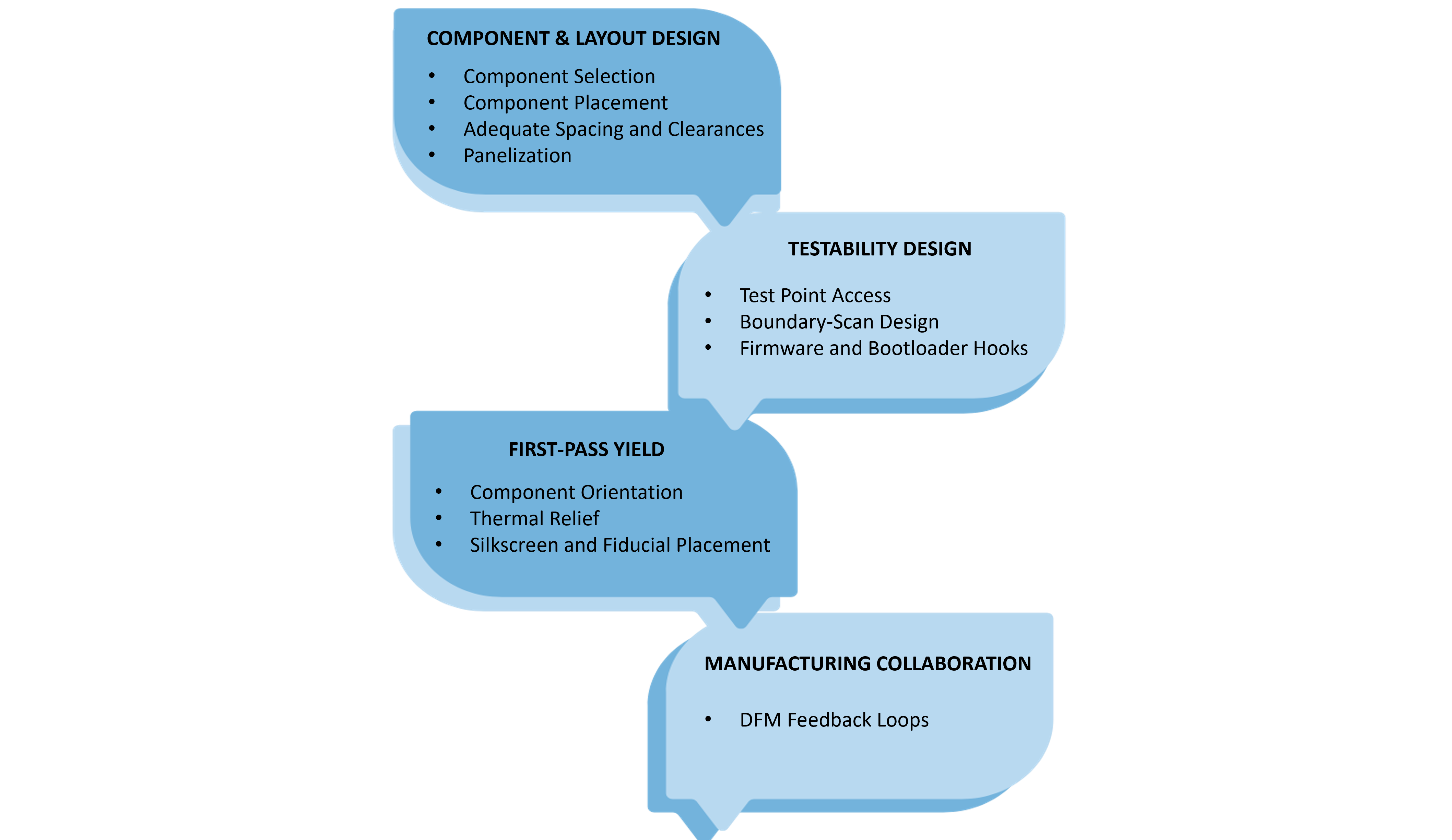
What is design for manufacturability? It's the practice of making component selection, placement, and layout decisions during design specifically to make the resulting board easier, faster, and higher-yield to manufacture, rather than optimizing the design purely for electrical performance or board size and treating manufacturability as the contract manufacturer's problem to solve afterward. What is design for manufacturability, in practice, comes down to a set of concrete choices: component footprints and packages the assembly process handles reliably, adequate spacing and clearances for placement and reflow tolerances, and panel layouts that use production-line real estate efficiently, all decided with the actual manufacturing process in mind rather than in isolation from it.
A design review that treats DFM and DFT as a final check before release, rather than a constraint considered from the first layout pass, routinely produces a board that technically works but is expensive or slow to manufacture and test. Once a layout is finalized, decisions like component placement, test point location, and panelization are difficult and costly to revisit without triggering another full design and validation cycle, which is exactly why the automotive electronics manufacturing programs with the best production outcomes treat design for manufacturing DFM and manufacturing and test engineers as design-phase stakeholders, not downstream reviewers brought in after the fact.
Design for testability dft in embedded systems means designing the board so that its functional correctness, and eventual manufacturing defects, can actually be verified efficiently once it's built, through accessible test points, boundary-scan-compatible component selection, and firmware or bootloader hooks that support production test sequencing. Design for testability DFT in embedded systems is inseparable from the end-of-line test strategy that will eventually run against the finished board, a design with poor test access forces a production test program to either accept reduced coverage or accept a much slower, more manual test process, neither of which is a good outcome for a high-volume automotive program. Design for testability dft in embedded systems decisions made early, before layout is locked, are far cheaper than the same decisions made as a retrofit.
Test point access and boundary-scan design for automated ecu testing determines how effectively an ECU can be probed by bed-of-nails fixtures or flying-probe testers during production, and how much of the board's connectivity can be verified through JTAG-based boundary scan without needing direct physical probe access at all. Test point access and boundary-scan design for automated ECU testing has to be planned early because test point placement competes directly with layout density and component placement decisions, a board designed without test access in mind often can't be retrofitted with adequate test points without compromising the layout that's already been finalized.
At automotive production volumes, panelization strategy, how many individual boards get manufactured together on a single production panel, and component placement relative to panel breakout lines, directly affects manufacturing throughput and cost per unit in a way that's largely invisible at prototype quantities. Components placed too close to panel edges or breakout tabs risk mechanical stress damage during depanelization, and panel layouts that don't account for the automated placement equipment's actual capabilities leave manufacturing efficiency on the table across every production run for the life of the program.
Dfm for electronics in an automotive context ultimately comes down to reducing the design choices that create first-pass yield problems: component orientations prone to tombstoning during reflow, insufficient thermal relief around ground planes that causes inconsistent solder joints, and silkscreen or fiducial placement that doesn't give automated optical inspection what it needs to verify placement accuracy. DFM for electronics decisions made correctly at design time show up months later as a production line that runs at target yield from the first qualified build, rather than one that spends its early production weeks chasing yield issues that could have been designed out before layout was ever released.
The contract manufacturer running production has direct, practical knowledge of what its specific line handles well and where it struggles, which makes a structured DFM feedback loop with the CM, design-for-manufacturing review at defined program milestones, not just a one-time check before release, one of the highest-leverage practices available to an automotive ECU program. Programs that treat CM DFM feedback as an ongoing collaboration throughout design, rather than a gate the design has to pass once, consistently catch manufacturability issues while they're still cheap to fix, before layout finalization rather than after the first production build already reveals them.
DFM and DFT decisions made during design directly determine what's achievable in the end-of-line test strategy that comes later; a board designed with genuine test access and boundary-scan coverage gives production test engineers real options, while one designed without that consideration in mind constrains every choice downstream. Our end-of-line testing article covers how that production test strategy gets built; this article is best read as its design-phase counterpart, since the two disciplines succeed or struggle together.
Embien Technologies applies design for manufacturing DFM and design-for-test principles across automotive ECU programs, from component selection and panelization through test point and boundary-scan planning, working directly with contract manufacturers to close DFM feedback loops before layout is finalized. See our companion end-of-line testing strategy article for how these design-phase decisions carry through to production test.
To discuss DFM/DFT review for an upcoming automotive ECU design, reach out to Embien's engineering team.

Embien's Product Engineering Services cover embedded hardware and software design, prototyping, testing, validation, and production-ready product development.

Embien's Automotive Electronics engineering supports ECU development, embedded hardware and software, vehicle connectivity, diagnostics, and automotive product development.
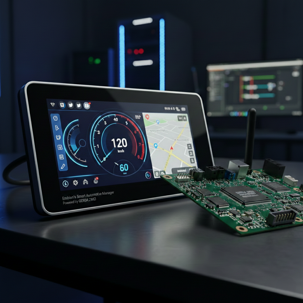
A case study on developing a low-cost evaluation kit for the GERDA Zwei MCU, covering embedded hardware design, board development, and validation.