
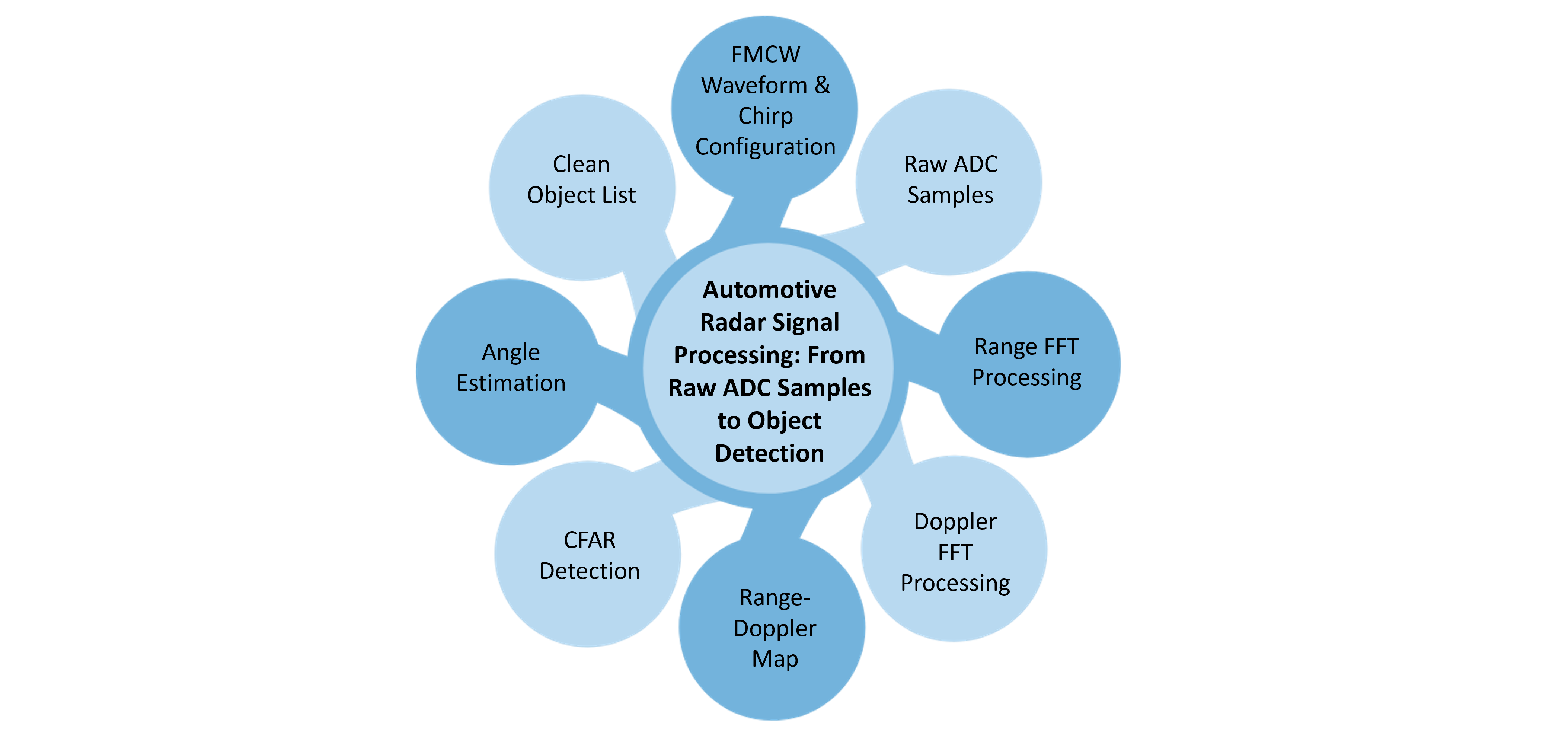
Our ADAS Sensor Fusion ECU Architecture Design article treats radar as one input feeding a fusion-layer decision, alongside camera and lidar object lists. Automotive radar signal processing: from raw ADC samples to object detection goes underneath that fusion layer, into how a radar sensor itself turns a set of raw analog-to-digital converter samples off its receive antennas into the range, velocity, and angle measurements the fusion layer actually consumes as a clean object list.

FMCW radar fundamentals for automotive range and velocity extraction start with the frequency-modulated continuous wave waveform nearly every automotive radar transmits: a linear chirp sweeping frequency over time, reflected back by a target, and mixed with the transmitted signal to produce a beat frequency proportional to the target's range. FMCW radar fundamentals for automotive range and velocity extraction get velocity from a second dimension entirely, the phase shift between successive chirps in a frame, which is proportional to the target's Doppler shift and therefore its relative radial velocity. A single chirp gives range; a full frame of many chirps is what actually gives velocity, which is why automotive radar signal processing works on frames of chirps rather than one chirp at a time.
The raw output off a radar's ADC is a large block of digitized samples across every chirp in a frame and every receive antenna, and turning that into something a detection algorithm can use is a specific, well-established signal processing chain. A first FFT across samples within each chirp resolves range, a second FFT across chirps within each frame resolves Doppler velocity, and the result is a range-Doppler map, a two-dimensional grid where each cell's magnitude represents reflected energy at that specific range and velocity combination. Automotive radar signal processing: from raw ADC samples to object detection depends entirely on this two-stage FFT chain producing a clean range-Doppler map before any detection logic runs on top of it.
CFAR detection and range-Doppler map processing for automotive radar is how a raw range-Doppler map, full of both genuine target returns and background noise and clutter, becomes an actual list of detected objects. Constant False Alarm Rate (CFAR) detection sets an adaptive threshold for each cell in the range-Doppler map based on the noise level in surrounding cells, rather than a single fixed threshold, so the detector stays sensitive in low-clutter regions while not flooding the output with false detections in high-clutter regions like a guardrail return or ground clutter. CFAR detection and range-Doppler map processing for automotive radar has to be tuned specifically for the automotive environment, where clutter characteristics change constantly with road surface, weather, and surrounding traffic density.
How does angle estimation work in automotive radar antenna arrays? A single receive antenna gives range and velocity but no angular information; angle comes from comparing the phase of a reflected signal as it arrives at multiple receive antennas spaced a known distance apart, since a target off-axis produces a slightly different path length, and therefore a slightly different phase, at each antenna. More receive antennas, and MIMO techniques that synthesize a larger virtual antenna array from a smaller number of physical transmit and receive elements, improve angular resolution, the ability to distinguish two targets at similar range and velocity but different angles, at the cost of more signal processing complexity per frame. How angle estimation works in automotive radar antenna arrays is ultimately a tradeoff between antenna count, angular resolution, and the processing budget available to run the angle-estimation algorithm on every frame.
Real-time radar processing within automotive safety-relevant latency budgets constrains every choice covered above, FFT sizes, CFAR window sizes, and angle-estimation algorithm complexity all have to fit within a processing budget measured in milliseconds per frame, because a radar feeding an emergency braking or adaptive cruise function has to deliver an updated object list fast enough for the vehicle to act on it before a closing-distance scenario becomes unrecoverable. Real-time radar processing within automotive safety-relevant latency budgets is typically implemented on dedicated radar processor silicon or DSP cores rather than general-purpose compute, specifically because the FFT and CFAR stages are extremely well suited to fixed, deterministic hardware pipelines that can guarantee a worst-case processing time.
Once automotive radar signal processing: from raw ADC samples to object detection has produced a clean object list, range, velocity, and angle for each detected target, that list becomes one input stream into the sensor fusion architecture covered in our ADAS sensor fusion ECU architecture design article, combined there with camera and, on some platforms, lidar object lists into a single fused environmental model. The buyer-facing question of when radar, camera, or a combination of both is the right sensor choice for a given ADAS function is covered separately in our blog post Automotive Camera and Radar Integration for ADAS Sensor Selection; this article covers what happens inside the radar sensor itself once that selection has already been made.
Radar's signal processing chain, from raw samples to a clean object list, mirrors a similar raw-to-usable transformation that happens on the camera side of an ADAS sensor suite, covered in our sibling article on the automotive camera ISP pipeline. Both sensors demand dedicated, deterministic processing hardware to turn a raw sensor feed into a usable perception input within the same automotive safety-relevant latency budget, even though the underlying signal processing techniques, FFTs and CFAR for radar, demosaicing and tone mapping for camera, are entirely different.
Embien Technologies designs automotive radar signal processing: from raw ADC samples to object detection for ADAS programs, including FMCW waveform and chirp configuration, range-Doppler processing chain implementation, CFAR detection tuning, and angle-estimation algorithm development on real-time, safety-relevant automotive processing hardware. To discuss a radar signal processing implementation for an upcoming ADAS program, reach out to Embien's sensor engineering team.

Edge Computing Services enable real-time processing of sensor data through optimized embedded compute platforms, supporting low-latency analytics and intelligent decision-making for automotive and ADAS applications.

Embien's Automotive Engineering Services cover embedded hardware and software development, vehicle networking, diagnostics, and integration for advanced automotive systems.
A case study on developing an i.MX8-based Android automotive smart cluster, covering embedded platform integration, display functionality, and automotive software development.